


7
Heat & Glo • SL-550 / 750 / 950TR-D • InD • 2044-985 Rev. M • 10/06
I
B
G
H
C
A
D
E
F
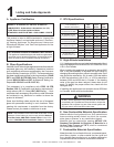
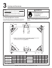
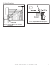
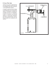
In addition to these framing dimensions, also reference the following sections:
• Clearances and Mantel Projections (Section 3.C and 3.D)
• Vent Clearances and Framing (Section 6).
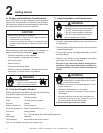
3
Framing and Clearances
NOTE:
• Illustrations refl ect typical installations and are FOR DESIGN
PURPOSES ONLY.
• Illustrations/diagrams are not drawn to scale.
• Actual installation may vary due to individual design
preference.
Fire Risk
Provide adequate clearance:
• Around air openings
• To combustibles
• For service access
Locate appliance away from traffi c areas.
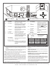
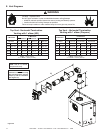
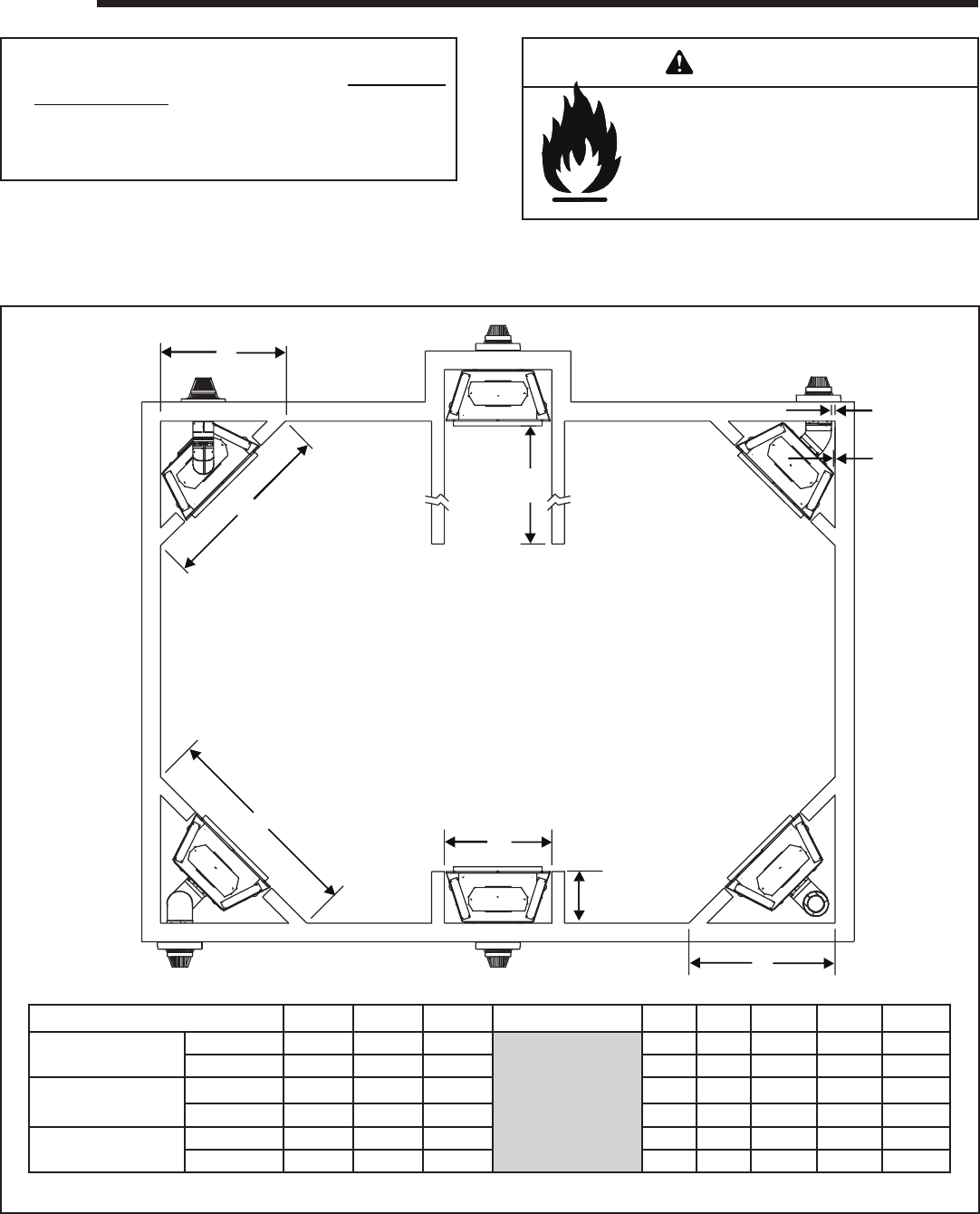
A. Selecting Appliance Location
When selecting a location for your appliance it is important to
consider the required clearances to walls (see Figure 3.1).
Figure 3.1 Appliance Locations
NOTE: For actual appliance dimensions refer to Sec-
tion 16.
WARNING
Models A B C D E F G H I
SL-550TR-IPI-D
SL-550TR-D
Inches 41-1/2 37 58-3/4
See Section D for
Alcove Installation
1 1/2 48-1/2 68-1/4 16-1/4
Millimeters 1054 940 1492 25 13 1232 1734 413
SL-750TR-IPI-D
SL-750TR-D
Inches 45 42 63-3/4 1 1/2 52 73-1/4 16-1/4
Millimeters 1143 1067 1619 25 13 1321 1861 413
SL-950TR-IPI-D
SL-950TR-D
Inches 50 49 70-3/4 1 1/2 57 80-1/4 16-1/4
Millimeters 1270 1245 1797 25 13 1448 2038 413