


Heat & Glo • SL-550 / 750 / 950TR-D • InD • 2044-985 Rev. M • 10/0640
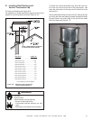
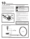
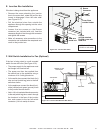
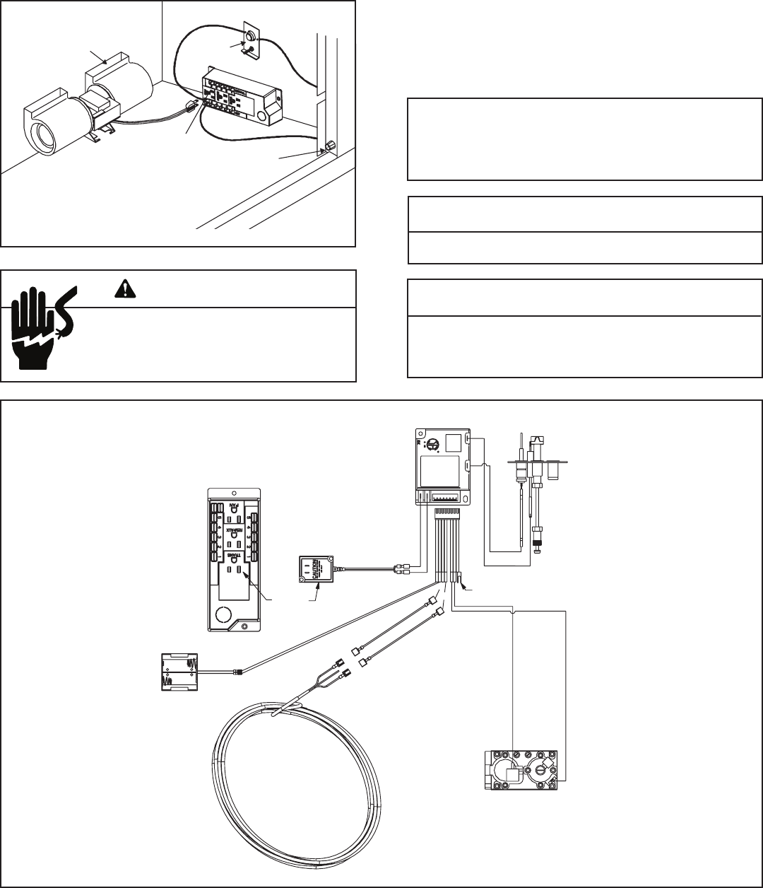
D. Intellifi re Ignition System Wiring
This appliance requires a 110 VAC supply to the appliance
junction box for operation. A wiring diagram is shown in
Figure 10.5.
This appliance is equipped with an Intellifi re control valve
which operates on a 3 volt system.
This appliance is supplied with a battery pack and a 3 volt AC
transformer, which requires the installation of the supplied
junction box. It is highly recommended that the junction box
be installed at this time to avoid reconstruction.
The battery pack requires two D cell batteries (not
included).
CAUTION
Battery polarity must be correct or module damage will occur.
CAUTION
Label all wires prior to disconnection when servicing controls.
Wiring errors can cause improper and dangerous operation.
Verify proper operation after servicing.
Shock hazard.
• Replace damaged wire with type 105º C
rated wire.
• Wire must have high temperature insulation.
Batteries cannot be placed in the battery pack while
using the 3 volt AC transformer. The transformer must
be unplugged if the battery pack is used or battery life
will be reduced.
WARNING
TRANSFORMER
3 VAC
PLUG IN
BLACK
RED
BATTERY PACK
THERMOSTAT
WIRE ASSEMBLY
JUMPER WIRE
(TO BROWN)
ORANGE
GREEN
VALVE
GROUND TO
FIREPLACE
CHASSIS
WHITE
ORANGE
IGNITION MODULE 3 VAC INTERMITTENT PILOT IGNITOR
HOT
NEUTRAL
I
S
Figure 10.4 Intellifi re Ignition Wiring Diagram
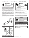
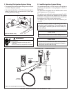
C. Standing Pilot Ignition System Wiring
• This standing pilot ignition system wiring does not require
a 110 VAC supply to operate.
• It is recommended that a 110 VAC junction box be in-
stalled for use with a fan or remote control. (See Figure
10.5 for junction box wiring).
Figure 10.3 Blower wiring
BLOWER
SENSOR
SWITCH
FAN
RECEPTACLE
SPEED
CONTROL