


Heat & Glo • SL-550 / 750 / 950TR-D • InD • 2044-985 Rev. M • 10/0630
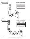
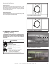
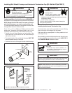
Assembling DVP-12A Slip Sections
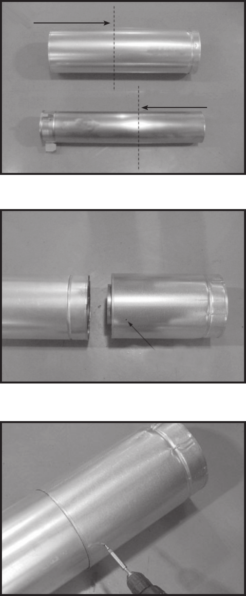
The outer fl ue of the slip section should slide over the outer
fl ue of the pipe section and into (inner fl ue) the last pipe
section (see Figure 8.6) .
Slide together to the desired length, making sure that a
1-1/2 inch outer fl ue overlap is maintained between the
pipe section and slip section.
The pipe and slip section need to be secured by driving
two screws through the overlapping portions of the outer
fl ues using the pilot holes (see Figure 8.7).
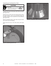
This will secure the slip section to the desired length and
prevent it from separating. The slip section can then be
attached to the next pipe section.
If the slip section is too long, the inner and outer fl ues of
the slip section can be cut to the desired length.
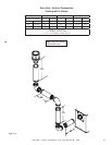
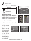
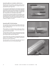
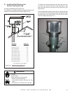
Assembling Minimum Installations (MI) Sections
MI sections are non-unitized so that they can be cut to a
certain length. Cut these sections to length from the non-
expanded end (see Figure 8.5).
They can then be attached by fi rst connecting the expanded
end of the MI inner fl ue with the inner pipe from the adjacent
pipe section and securing with three screws. The expanded
portion of the MI inner fl ue must overlap completely with
the unexpanded end of the adjacent pipe section.
The outer fl ue can then be inserted into the adjacent outer
fl ue expanded end and attached to the next pipe section
with three screws. The other end of the MI pipe section can
then be attached by fi tting another pipe section to it and
snapping it together, as normal.
Figure 8.6 Slip Section Pilot Holes
Figure 8.7 Screws into Slip Section
Figure 8.5
Cut from this end
Cut from this end
(inner)
(outer)
Pilot hole