


Heat & Glo • SL-550 / 750 / 950TR-D • InD • 2044-985 Rev. M • 10/0632
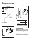
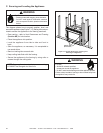
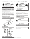
For Vertical Runs - The vent system must be supported
every eight (8) feet (2.4m) above the appliance fl ue outlet by
wall brackets. To install support brackets for vertical runs:
• Attach wall brackets to the vent pipe and secure the wall
bracket to the framing members with nails or screws.
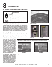
Continue Adding Vent Components
• Continue adding vent components, locking each suc-
ceeding component into place.
• Ensure that each succeeding vent component is securely
fi tted and locked into the preceding component.
• 90° elbows may be installed and rotated to any point
around the preceding component’s vertical axis. If an
elbow does not end up in a locked position with the
preceding component, attach with a minimum of two (2)
sheet metal screws.
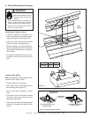
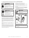
Figure 8.12 Adding Venting Components
Install Support Brackets
For Horizontal Runs - The vent system must be supported
every fi ve (5) feet of horizontal run by a horizontal pipe
support.
To install support brackets for horizontal runs:
• Place the pipe supports around the vent pipe.
• Nail the pipe supports to the framing members.
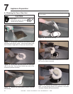
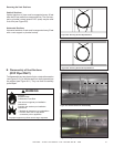
Attach the First Vent Component to Starting Collars
To attach the fi rst vent component to the starting collars
of the appliance:
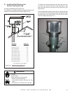
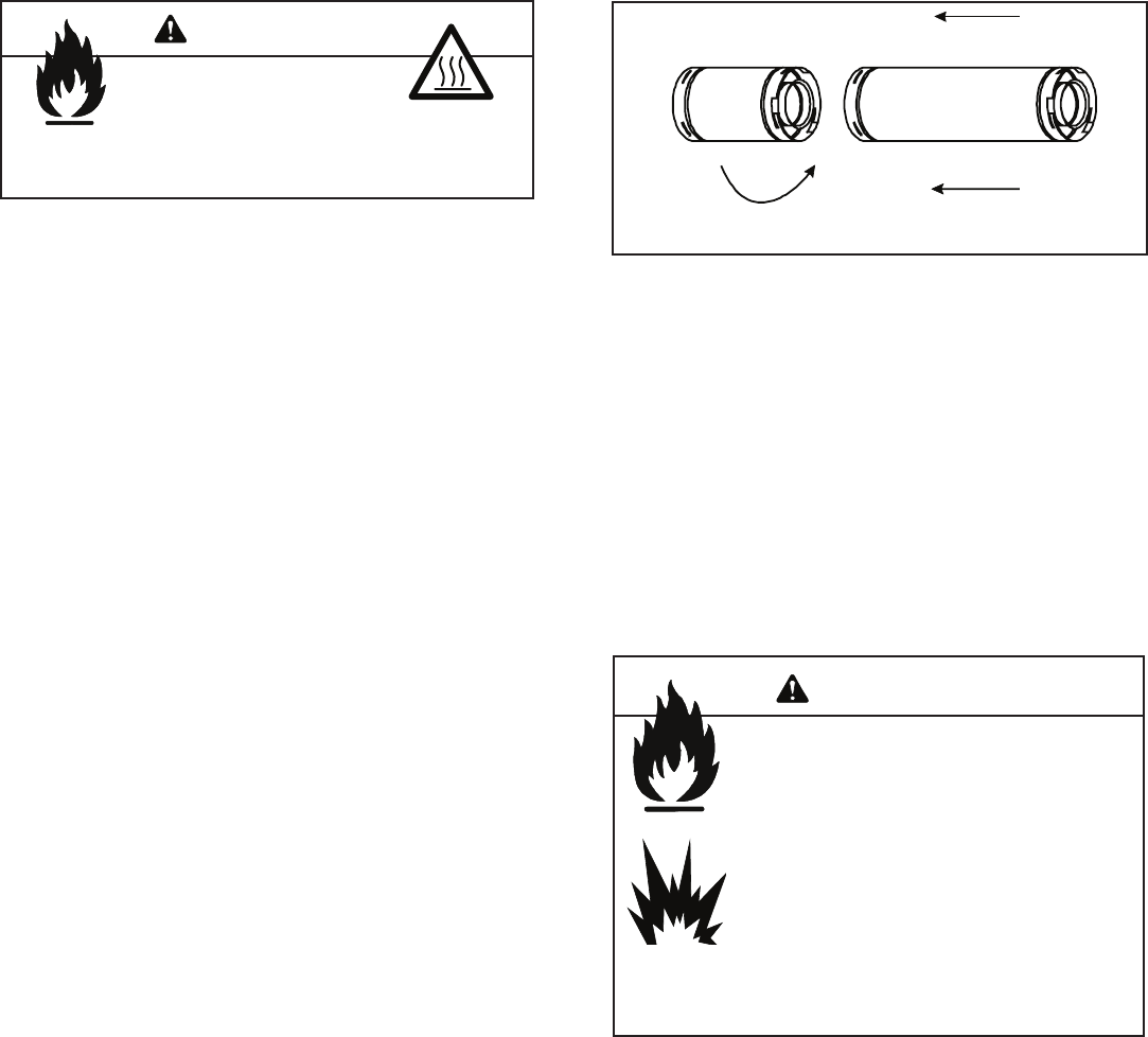
• Lock the vent components into place by sliding the
concentric pipe sections with four (4) equally spaced in-
terior beads into the appliance collar or previously installed
component end with four (4) equally spaced indented sec-
tions.
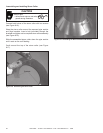
• When the internal beads of each outer pipe line up, ro-
tate the pipe section clockwise about one-quarter (1/4)
turn (see Figure 8.13). The vent pipe is now locked
together.
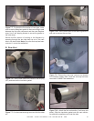
• Slide the ceramic fi ber pad over the fi rst vent section
and place it fl ush to the appliance. This will prevent cold
air infi ltration. High temp caulk may be used to hold the
part in place. Continue to add vent components.
Fire Risk
Exhaust Fumes Risk
Impaired Performance of Appliance
• Ensure vent components are locked together correctly.
• Pipe may separate if not properly joined.
Fire Risk.
Explosion Risk.
Combustion Fume Risk.
Use vent run supports per installation
instructions.
Connect vent sections per installation
instructions.
• Maintain all clearances to combustibles.
• Do NOT allow vent to sag below
connection point to appliance.
• Maintain specifi ed slope (if required).
Improper support may allow vent to sag or separate.
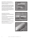
Assembly of Vent Sections (SL Series Pipe ONLY)
WARNING
WARNING