


61
Heat & Glo • SL-550 / 750 / 950TR-D • InD • 2044-985 Rev. M • 10/06
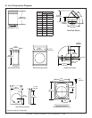
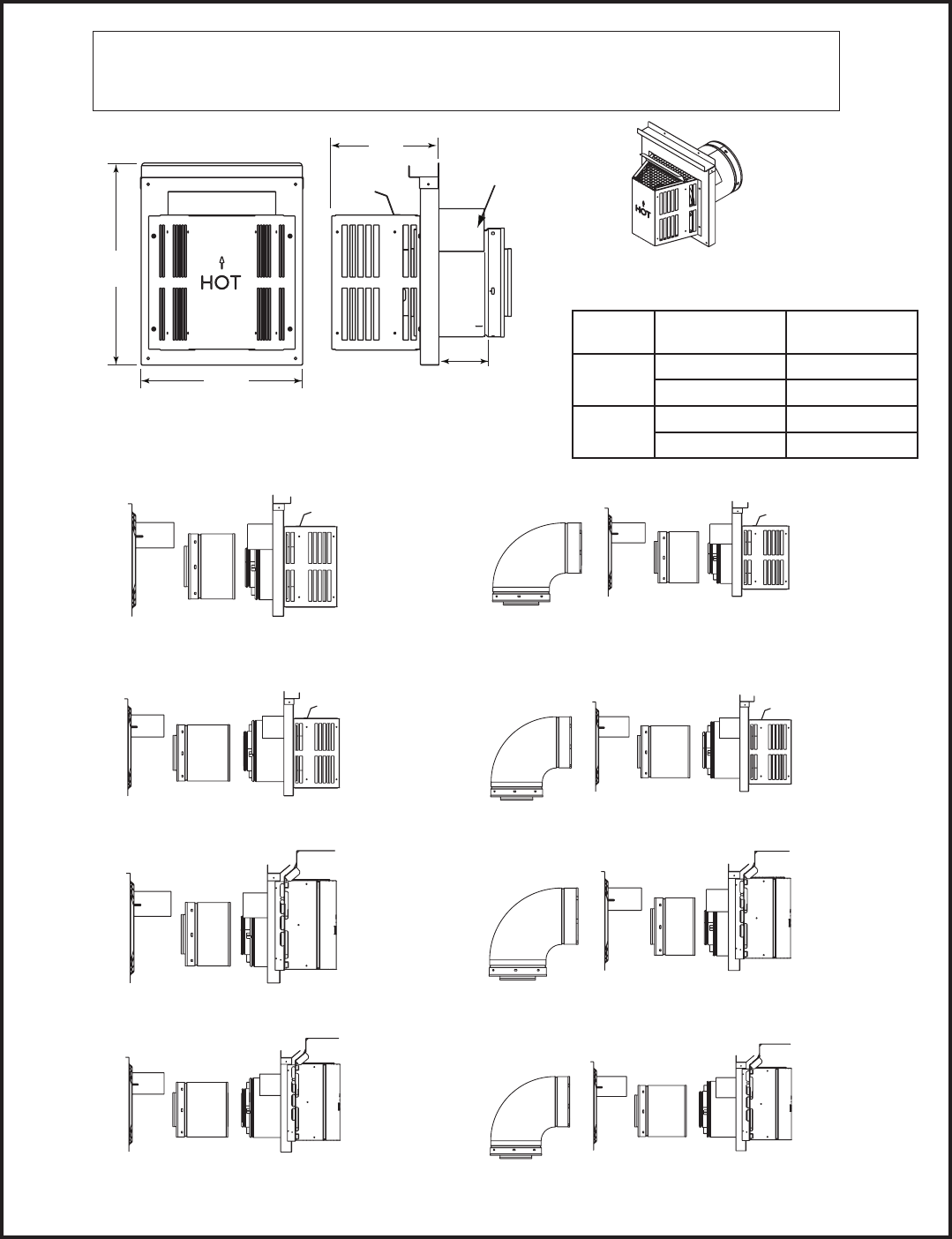
B. Vent Components Diagrams (continued)
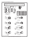
Figure 16.3 DVP vent components
DVP-HPC1
DVP-HPC2
DVP-TRAP1
DVP-TRAP2
DVP-HPCK1-B
DVP-HPCK2-B
DVP-TRAPK1
DVP-TRAPK2
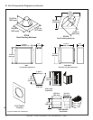
DVP-TRAP
Horizontal Termination Cap
15-1/8 in.
(384 mm)
12 in.
(305 mm)
8 in.
(203 mm)
Max
Effective
Length
Note: Heat shields MUST overlap by a minimum of 1-1/2 in. (38 mm). The heat shield is designed to be
used on a wall 4 in. to 7-1/4 in. (102 mm to 184 mm) thick. If wall thickness is less than 4 in. (102 mm) the
existing heat shields must be field trimmed. If wall thickness is greater than 7-1/4 in. (184 mm) a DVP-HSM-B
will be required.
Heat
Shield
Term Cap
Minimum
Effective Length
Maximum
Effective Length
Trap1
4-1/8 in. 5-5/8 in.
105 mm 143 mm
Trap2
6-3/4 in. 10-5/8 in.
171 mm 270 mm