


34
G
AS
S
UPPLY
AND
P
IPING
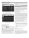
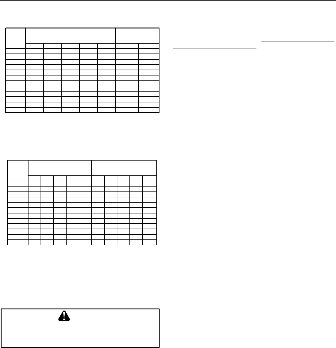
3/8" 1/2" 5/8" 3/4" 7/8" 1/2" 3/4"
10 730 1,700 3,200 5,300 8,300 3,200 7,500
20 500 1,100 220 3,700 5,800 2,200 4,200
30 400 920 2,000 2,900 4,700 1,800 4,000
40 370 850 1,700 2,700 4,100 1,600 3,700
50 330 770 1,500 2,400 3,700 1,500 3,400
60 300 700 1,300 2,200 3,300 1,300 3,100
80 260 610 1,200 1,900 2,900 1,200 2,600
100 220 540 1,000 1,700 2,600 1,000 2,300
125 200 490 900 1,400 2,300 900 2,100
150 190 430 830 1,300 2,100 830 1,900
175 170 400 780 1,200 1,900 770 1,700
200 160 380 730 1,100 1,800 720 1,500
Pipe or
Tubing
Length
Feet
Tubing Size, O.D. Type L
Nominal Pipe Size
Schedule 40
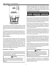
Sizing Between First and Second Stage Regulator*
Maximum Propane Capacities listed are based on 2 psig pressure drop at 10 psig setting.
Capacities in 1,000 BTU/hour.
To convert to capacities at 15 psig settings - multiply by 1.130
To convert to capacities at 5 psig settings - multiply by 0.879
Propane Gas Piping Chart I
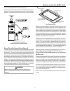
3/8" 1/2" 5/8" 3/4" 7/8" 1/2" 3/4" 1" 1-1/4" 1-1/2"
10 39 92 199 329 501 275 567 1,071 2,205 3,307
20 26 62 131 216 346 189 393 732 1,496 2,299
30 21 50 107 181 277 152 315 590 1,212 1,858
40 19 41 90 145 233 129 267 504 1,039 1,559
50 18 37 79 131 198 114 237 448 913 1,417
60 16 35 72 1,211 187 103 217 409 834 1,275
80 13 29 62 104 155 89 185 346 724 1,066
100 11 26 55 90 138 78 162 307 630 976
125 10 24 48 81 122 69 146 275 567 866
150 9 21 43 72 109 63 132 252 511 787
200 8 19 39 66 100 54 112 209 439 665
250 8 17 36 60 93 48 100 185 390 590
Tubing Size, O.D. Type L
Nominal Pipe Size
Schedule 40
Pipe or
Tubing
Length
Feet
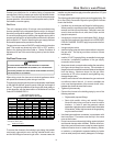
*Data in accordance with NFPA pamphlet No. 54
Sizing Between Second or Second Stage Regulator & Appliance*
Maximum Propane Capacities listed are based on 1/2" W.C. pressure drop at 11" W.C. setting.
Capacities in 1,000 BTU/hour.
Propane Gas Piping Chart II
C
IRCULATING
A
IR
& F
ILTERS
DUCT WORK - AIR F LOW
N
EVER
ALLOW
THE
PRODUCTS
OF
COMBUSTION
,
INCLUDING
CARBON
MONOXIDE
,
TO
ENTER
THE
RETURN
DUCT
WORK
OR
CIRCULATION
AIR
SUPPLY
.
WARNING
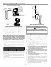
Duct systems and register sizes must be properly designed for
the CFM and external static pressure rating of the furnace. Design
the ductwork in accordance with the recommended methods of
“Air Conditioning Contractors of America” Manual D.
Install the duct system in accordance with Standards of the Na-
tional Board of Fire Underwriters for the Installation of Air Condition-
ing, Warm Air Heating and Ventilating Systems. Pamphlets No.
90A and 90B.
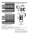
A closed return duct system must be used, with the return duct
connected to the furnace. NOTE:
Ductwork must never be at-
tached to the back of the furnace. For upflow installations requir-
ing 1800 CFM or more, use either two side returns or bottom
return or a combination of side /bottom. Flexible joints may be
used for supply and return connections to reduce noise transmis-
sion. To prevent the blower from interfering with combustion air or
draft when a central return is used, a connecting duct must be
installed between the unit and the utility room wall. Never use a
room, closet, or alcove as a return air chamber.
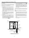
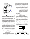
CHECKING D UCT S TATIC
Refer to your furnace rating plate for the maximum ESP (ex-
ternal duct static) rating.
Total external static refers to everything external to the fur-
nace cabinet. Cooling coils, filters, ducts, grilles, registers
must all be considered when reading your total external static
pressure. The supply duct pressure must be read between
the furnace and the cooling coil. This reading is usually taken
by removing the “A” shaped block off plate from the end on the
coil; drilling a test hole in it and reinstalling the block off plate.
Take a duct static reading at the test hole. Tape up the test
hole after your test is complete. The negative pressure must
be read between the filter and the furnace blower.
Too much external static pressure will result in insufficient air
that can cause excessive temperature rise. This can cause
limit switch tripping and heat exchanger failure.
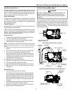
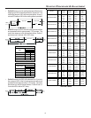
To determine total external duct static pressure, proceed as
follows;
1. With clean filters in the furnace, use a draft gauge (in-
clined manometer) to measure the static pressure of the
return duct at the inlet of the furnace. (Negative Pressure)
2. Measure the static pressure of the supply duct. (Positive
Pressure)
3. The difference between the two numbers is .4” w.c.
Example:
static reading from return duct = -.1" w.c.
static reading from supply duct = .3" w.c.
total external static pressure on this system = .4" w.c.
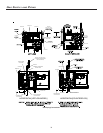
NOTE: Both readings may be taken simultaneously and read
directly on the manometer if so desired. If an air conditioner
coil or Electronic Air Cleaner is used in conjunction with the
furnace, the readings must also include theses components,
as shown in the following drawing.