


38
S
TARTUP
P
ROCEDURE
& A
DJUSTMENT
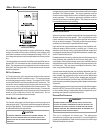
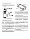
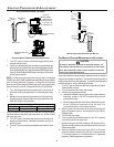
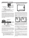
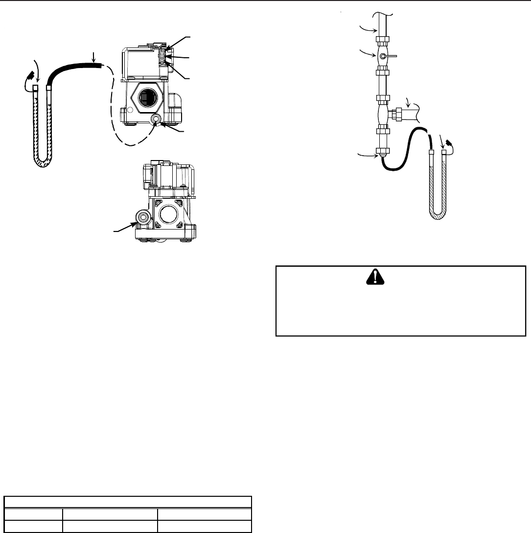
Honeywell Model VR9205 (Two-Stage)
i
M
a
n
o
m
e
t
e
r
M
a
n
o
m
e
t
e
r
H
o
s
e
Common
Terminal(C)
High Fire Coil
Terminal (HI)
Low Fire Coil
Terminal (LO)
Inlet Pressure Tap
1/8 NPT
O
p
e
n
t
o
A
t
m
o
s
p
h
e
r
e
Outlet Pressure Tap
1/8 NPT
Honeywell Model VR9205 Connected to Manometer
1. Turn OFF gas to furnace at the manual gas shutoff valve
external to the furnace.
2. Connect a calibrated water manometer (or appropriate gas
pressure gauge) at either the gas valve inlet pressure boss
or the gas piping drip leg. See Honeywell VR9205 gas valve
figure or White-Rodgers 36G54 gas valve figure for location
of inlet pressure boss.
NOTE: If measuring gas pressure at the drip leg or Honeywell
VR9205 gas valve, a field-supplied hose barb fitting must be installed
prior to making the hose connection. If using the inlet pressure
boss on the White-Rodgers 36G54 gas valve, then use the 36G
Valve Pressure Check Kit, Goodman Part No. 0151K00000S.
3. Turn ON the gas supply and operate the furnace and all
other gas consuming appliances on the same gas supply
line.
4. Measure furnace gas supply pressure with burners firing.
Supply pressure must be within the range specified in the
Inlet Gas Supply Pressure table.
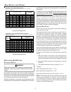
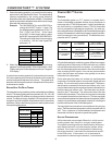
Natural Gas
Minimum: 5.0" w.c. Maximum:10.0" w.c.
Propane Gas
Minimum: 11.0" w.c. Maximum:13.0" w.c.
Inlet Gas Supply Pressure
If supply pressure differs from table, make the necessary adjust-
ments to pressure regulator, gas piping size, etc., and/or consult
with local gas utility.
5. Turn OFF gas to furnace at the manual shutoff valve and
disconnect manometer. Reinstall plug before turning on
gas to furnace.
6. Turn OFF any unnecessary gas appliances stated in step
3.
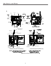
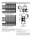
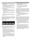
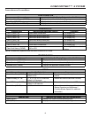
Gas Line
Gas
Shutoff
Valve
Gas Line
To Furnace
Drip Leg Cap
With Fitting
Manometer Hose
Manometer
Open To
Atmosphere
Measuring Inlet Gas Pressure (Alt. Method)
GAS M ANIFOLD P RESSURE M EASUREMENT AND A DJUSTMENT
T
O
PREVEN T
UNRELIABLE
OPERATION
OR
EQUIPMENT
DAMAGE
,
THE
GAS
MANIFOLD
PRESSURE
MUST
BE
AS
SPECIFIED
ON
THE
UNIT
RATING
PLATE
.O
NLY
MINOR
ADJUSTMENTS
SHOULD
BE
MADE
BY
ADJUSTING
THE
GAS
VALVE
PRESSURE
REGULATOR
.
CAUTION
Only small variations in gas pressure should be made by adjusting
the gas valve pressure regulator. The manifold pressure must be
measured with the burners operating. To measure and adjust the
manifold pressure, use the following procedure.
1. Turn OFF gas to furnace at the manual gas shutoff valve
external to the furnace.
2. Turn off all electrical power to the system.
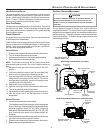
3. Outlet pressure tap connections:
a. Honeywell VR9205 valve: Remove the outlet pressure
boss plug. Install an 1/8" NPT hose barb fitting into the
outlet pressure tap.
b. White-Rodgers 36G54 valve: Back outlet pressure test
screw (inlet/outlet pressure boss) out one turn
(counterclockwise, not more than one turn).
4. Attach a hose and manometer to the outlet pressure barb
fitting (Honeywell valve) or outlet pressure boss (White-
Rodgers valve).
5. Turn ON the gas supply.
6. Turn on power and close thermostat “R” and “W1” contacts
to provide a call for low stage heat.
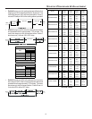
7. Measure the gas manifold pressure with burners firing.
Adjust manifold pressure using the Manifold Gas Pressure
table shown below.
8. Remove regulator cover screw from the low (LO) outlet
pressure regulator adjust tower and turn screw clockwise
to increase pressure or counterclockwise to decrease
pressure. Replace regulator cover screw.