


13
V
ENT
/F
LUE
P
IPE
& C
OMBUSTION
A
IR
P
IPE
T
O
AVOID
BODILY
INJURY
,
FIRE
OR
EXPLOSION
,
SOLVENT
CEMENTS
MUST
BE
KEPT
AWAY
FROM
ALL
IGNITION
SOURCES
(
I
.
E
.,
SPARKS
,
OPEN
FLAMES
,
AND
EXCESSIVE
HEAT
)
AS
THEY
ARE
COMBUSTIBLE
LIQUIDS
.
A
VOID
BREATHING
CEMENT
VAPORS
OR
CONTACT
WITH
SKIN
AND
/
OR
EYES
.
WARNING
Two- or three-inch nominal diameter PVC Schedule 40 pipe meet-
ing ASTM D1785, PVC primer meeting ASTM F656, and PVC
solvent cement meeting ASTM D2564 specifications must be used.
Fittings must be DWV type fittings meeting ASTM D2665 and
ASTM D3311. Carefully follow the pipe manufacturer’s instruc-
tions for cutting, cleaning, and solvent cementing of PVC.
The use of Schedule 40 PVC Cellular Core (Foam Core) plastic
pipe is also acceptable as a flue/vent and intake pipe material.
PVC primer meeting ASTM F656 and PVC solvent cement meet-
ing ASTM D2564 specifications must be used. Fittings must be
DWV type fittings meeting ASTM D2665 and ASTM D3311. Care-
fully follow the manufactures instructions for cutting, cleaning and
solvent cementing of PVC.
MATERIALS AND J OINING M ETHODS
As an alternative to PVC pipe, primer, solvent cement, and fittings,
ABS materials which are in compliance with the following specifi-
cations may be used. Two-or-three-inch ABS Schedule 40 pipe
must meet ASTM D1527 and, if used in Canada, must be CSA
listed. Solvent cement for ABS to ABS joints must meet ASTM
D2235 and, if used in Canada, must be CSA listed. The solvent
cement for the PVC to ABS transition joint must meet ASTM D3138.
Fittings must be DWV type fittings meeting ASTM D2661 and
ASTM D3311 and, if used in Canada, must be CSA listed. Care-
fully follow the manufacturers’ instructions for cutting, cleaning,
and solvent cementing PVC and/or ABS.
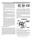
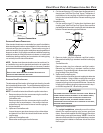
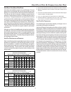
All 90° elbows must be medium radius (1/4 bend DWV) or long
radius (Long sweep 1/4 bend DWV) types conforming to ASTM
D3311. A medium radius (1/4 bend DWV) elbow measures 3 1/
16” minimum from the plane of one opening to the centerline of the
other opening for 2” diameter pipe, and 4 9/16” minimum for 3”
pipe.
PROPER V ENT/FLUE AND C OMBUSTION A IR P IPING P RACTICES
Adhere to these instructions to ensure safe and proper furnace
performance. The length, diameter, and number of elbows of the
vent/flue pipe and combustion air pipe (when applicable) affects
the performance of the furnace and must be carefully sized. All
piping must be installed in accordance with local codes and these
instructions.
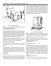
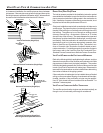
Piping must be adequately secured and supported to prohibit sag-
ging, joint separation, and/or detachment from the furnace. Hori-
zontal runs of vent/flue piping must be supported every three to five
feet and must maintain a 1/4 inch per foot downward slope, back
towards the furnace, to properly return condensate to the furnace’s
drain system. Allowances should be made for minor expansion
and contraction due to temperature variations. For this reason,
particular care must be taken to secure piping when a long run is
followed by a short offset of less than 40 inches.
Precautions should be taken to prevent condensate from freezing
inside the vent/flue pipe and/or at the vent/flue pipe termination. All
vent/flue piping exposed to freezing temperatures below 35°F for
extended periods of time must be insulated with 1/2” thick closed
cell foam. Also all vent/flue piping exposed outdoors in excess of
the terminations shown in this manual (or in unheated areas) must
be insulated with 1/2” thick closed cell foam. Inspect piping for
leaks prior to installing insulation.
TERMINATION L OCATIONS
NOTE: Refer to Location Requirements and Considerations for
combustion air contaminant restrictions.
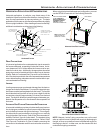
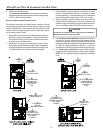
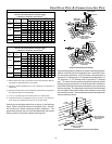
The following bullets and diagram describe the restrictions con-
cerning the appropriate location of vent/flue pipe and combustion
air intake pipe (when applicable) terminations. Refer to Non-Direct
Vent (Single Pipe) Piping and Direct Vent (Dual Pipe) Piping lo-
cated in this section for specific details on termination construc-
tion.
• All terminations (flue and/or intake) must be located at
least 12 inches above ground level or the anticipated snow
level.
• Vent terminations (non-direct and direct vent) must
terminate at least 3 feet above any forced air inlet located
within 10 feet.
NOTE: This provision does not apply to the combustion
air intake termination of a direct vent application.
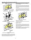
• The vent termination of a non-direct vent application must
terminate at least 4 feet below, 4 feet horizontally from,
or 1 foot above any door, window, or gravity air inlet into
any building.
• The vent termination of a direct vent application must
terminate at least 12 inches from any opening through
which flue gases may enter a building (door, window, or
gravity air inlet).
• The vent termination of vent pipe run vertically through a
roof must terminate at least 12 inches above the roof line
(or the anticipated snow level) and be at least 12 inches
from any vertical wall (including any anticipated snow
build up).
• A vent termination shall not terminate over public walkways
or over an area where condensate or vapor could create
a nuisance or hazard or could be detrimental to the
operation of regulators, relief valves, or other equipment.
• The combustion air intake termination of a direct vent
application should not terminate in an area which is
frequently dusty or dirty.