


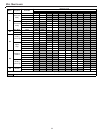
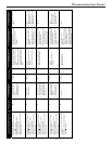
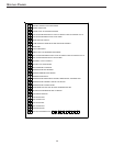

T
ROUBLESHOOTING
C
HART
53
ComfortNet™
Thermostat Only
Symptoms of Abnormal Operation (Legacy
& ComfortNet™ Thermostat)
Diagnostic/Status
LED Codes
Fault Description
Message Code
Possible Causes
Corrective Actions
Notes & Cautions
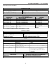
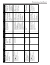
x Furnace fails to operate
x Integrated control module LED display
provides no signal.
x ComfortNet™ thermostat “Call for
Service” icon illuminated
x ComfortNet™ thermostat scrolls “Check
Furnace” message
None
x No 115 power to furnace
or no 24 volt power to
integrated control
module
x Blown fuse or circuit
breaker
x Integrated control
module has an internal
fault
INTERNAL
FAULT
EE
x Manual disconnect switch OFF,
door switch open or 24 volt wire
improperly connected or loose
x Blown fuse or circuit breaker
x Integrated control module has an
internal fault
x Assure 115 and 24 volt power to
furnace and integrated control
module.
x Check integrated control module
fuse (3A). Replace if necessary.
x Check for possible shorts in 115
and 24 volt circuits. Repair as
necessary.
x Replace bad integrated control
module.
x Turn power OFF prior to
repair.
x Replace integrated control
module fuse with 3A
automotive fuse.
x Read precautions in
“Electrostatic Discharge”
section of manual.
x Replace integrated control
module with current
replacement parts.
x LED display indicates
OP
OP
x Normal operation
None None
x Normal operation x None x Normal operation
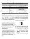
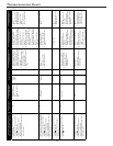
x Furnace fails to operate
x Integrated control module LED display
provides
E0
error code.
x ComfortNet™ thermostat “Call for
Service” icon illuminated.
x ComfortNet™ thermostat scrolls “Check
Furnace” message.
E0
x Furnace lockout due to
an excessive number of
ignition “retries” (3 total)
LOCKOUT E0
x Failure to establish flame. Cause
may be no gas to burners, front
cover pressure switch stuck open,
bad igniter or igniter alignment,
improper orifices, or
coated/oxidized or improperly
connected flame sensor.
x Loss of flame after establishment.
Cause may be interrupted gas
supply, lazy burner flames
(improper gas pressure or
restriction in flue and/or
combustion air piping), front
cover pressure switch opening, or
improper induced draft blower
performance.
x Locate and correct gas
interruption.
x Check front cover pressure
switch operation (hose, wiring,
contact operation). Correct if
necessary.
x Replace or realign igniter.
x Check flame sense signal. Sand
sensor if coated and/or oxidized.
x Check flue piping for blockage,
proper length, elbows, and
termination.
x Verify proper induced draft
blower performance.
x Turn power OFF prior to
repair.
x Igniter is fragile, handle
with care.
x Sand flame sensor with
emery cloth.
x See “Vent/Flue Pipe”
section for piping details.
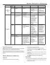
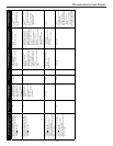
x Furnace fails to operate.
x Integrated control module LED display
provides
E1
error code.
x ComfortNet™ thermostat “Call for
Service” icon illuminated.
x ComfortNet™ thermostat scrolls “Check
Furnace” message.
E1
x Low stage pressure
switch circuit is closed at
start of heating cycle.
PS1
CLOSED
E1
x Low stage pressure switch
contacts sticking.
x Shorts in pressure switch circuit
wiring.
x Replace low stage pressure
switch.
x Repair short in wiring.
x Turn power OFF prior to
repair.
x Replace pressure switch
with correct replacement
part.
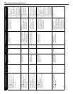
x Induced draft blower runs continuously
with no further furnace operation.
x Integrated control module LED display
provides
E2
error code.
x ComfortNet™ thermostat “Call for
Service” icon illuminated.
x ComfortNet™ thermostat scrolls “Check
Furnace” message.
E2
x Low stage pressure
switch circuit is not
closed.
PS1 OPEN E2
x Pressure switch hose blocked
pinched, or connected improperly.
x Blocked flue and/or inlet air pipe,
blocked drain system or weak
induced draft blower.
x Incorrect pressure switch set point
or malfunctioning switch
contacts.
x Loose or improperly connected
wiring.
x Inspect pressure switch hose.
Repair/replace if necessary.
x Inspect flue and/or inlet air
piping for blockage, proper
length, elbows, and termination.
x Check drain system. Correct as
necessary.
x Check induced draft blower
performance. Correct as
necessary.
x Correct pressure switch set point
or contact motion.
x Tighten or correct wiring
connection.
x Turn power OFF prior to
repair.
x Replace pressure switch
with correct replacement
part.
x Replace induced draft
blower with correct
replacement part.