


9
L
OCATION
R
EQUIREMENTS
& C
ONSIDERATIONS
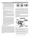
• If the furnace is used in connection with a cooling coil
unit, install the furnace upstream or in parallel with the
cooling coil unit. Premature heat exchanger failure will
result if the cooling unit is placed ahead of the furnace.
• If the furnace is installed in a residential garage, position
the furnace so that the burners and ignition source are
located not less than 18 inches (457 mm) above the
floor. Protect the furnace from physical damage by
vehicles.
• If the furnace is installed horizontally, ensure the access
doors are not on the “up/top” or “down/bottom” side of the
furnace.
• Do not connect this furnace to a chimney flue that serves
a separate appliance designed to burn solid fuel.
• On Counterflow Installations, the air conditioning coil must
be downstream on the supply (positive) side of the furnace
heat exchanger.
• Counterflow Installation over a noncombustible floor.
Before setting the furnace over the plenum opening, ensure
the surface around the opening is smooth and level. A
tight seal should be made between the furnace base and
floor by using a silicone rubber caulking compound or
cement grout.
• Counterflow Installation over a combustible floor. If
installation over a combustible floor becomes necessary,
use an accessory subbase (see Specification Sheet
applicable for your model for details.) A special accessory
subbase must be used for upright counterflow unit
installations over any combustible material including wood.
Refer to subbase instructions for installation details. Follow
the instructions with the subbase for proper installation.
Do not install the furnace directly on carpeting, tile, or
other combustible material other than wood flooring.
(NOTE: The subbase will not be required if an air
conditioning coil is installed between the supply air
opening on the furnace and the floor.)
CLEARANCES AND A CCESSIBILITY
Installations must adhere to the clearances to combustible mate-
rials to which this furnace has been design certified. The minimum
clearance information for this furnace is provided on the unit’s clear-
ance label. These clearances must be permanently maintained.
Clearances must also accommodate an installation’s gas, electri-
cal, and drain trap and drain line connections. If the alternate
combustion air intake or vent/flue connections are used additional
clearance must be provided to accommodate these connections.
Refer to Vent/Flue Pipe and Combustion Air Pipe for details. NOTE:
In addition to the required clearances to combustible materials, a
minimum of 24 inches service clearance must be available in front
of the unit.
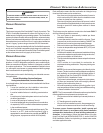
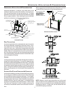
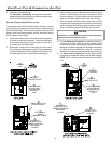
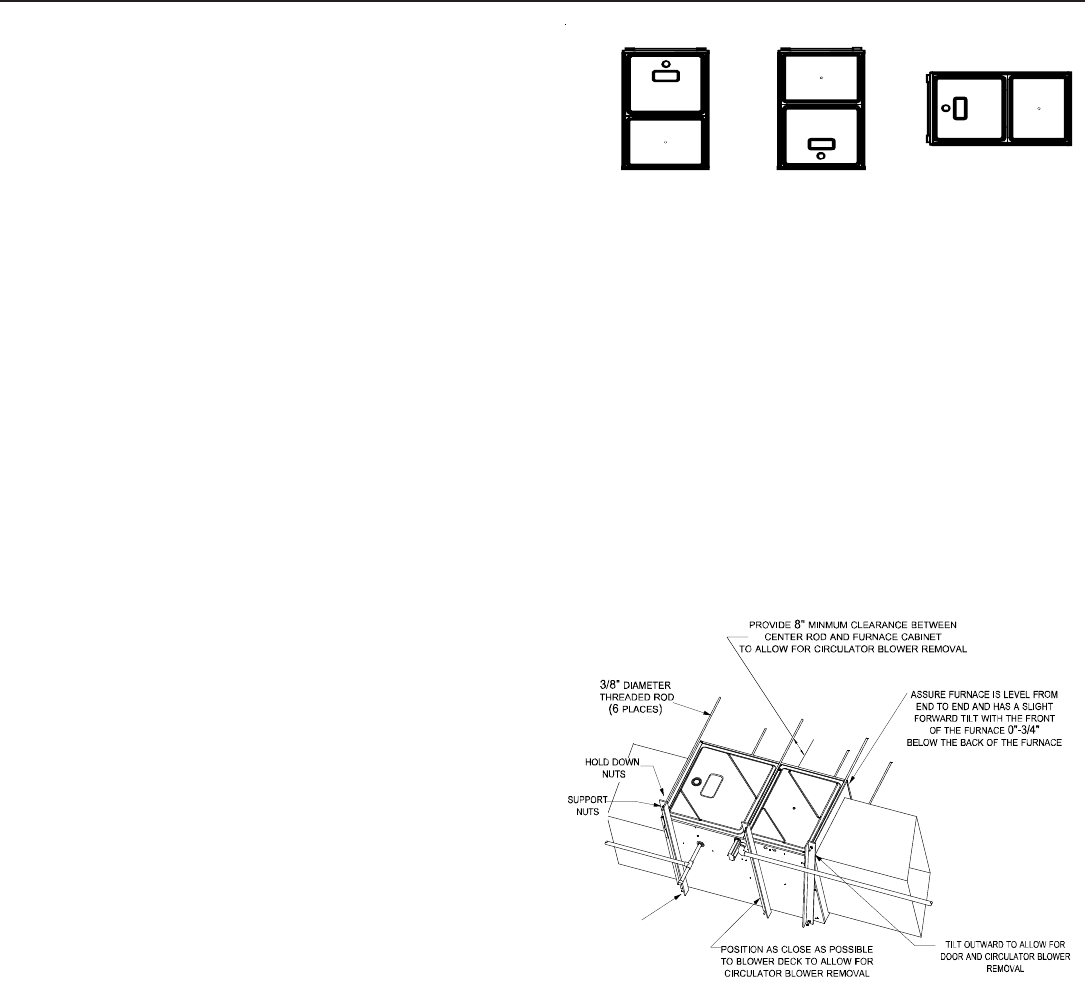
TOP
BOTTOM
SIDE SIDE SIDE
TOP
BOTTOM
Upflow Counterflow Horizontal
A furnace installed in a confined space (i.e., a closet or utility
room) must have two ventilation openings with a total minimum
free area of 0.25 square inches per 1,000 BTU/hr of furnace input
rating. Refer to Specification Sheet applicable to your model for
minimum clearances to combustible surfaces. One of the ventila-
tion openings must be within 12 inches of the top; the other open-
ing must be within 12 inches of the bottom of the confined space.
In a typical construction, the clearance between the door and door
frame is usually adequate to satisfy this ventilation requirement.
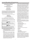
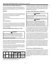
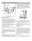
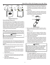
FURNACE SUSPENSION
If suspending the furnace from rafters or joists, use 3/8" threaded
rod and 2”x2”x1/8” angle iron as shown in the following diagram.
The length of rod will depend on the application and the clearances
necessary.
2" 2" 3/8"
ANGLE
IRON
(3
PLACES
)
XX
EXISTING F URNACE R EMOVAL
NOTE: When an existing furnace is removed from a venting sys-
tem serving other appliances, the venting system may be too large
to properly vent the remaining attached appliances.
The following vent testing procedure is reproduced from the American
National Standard/National Standard of Canada for Gas-Fired Central
Furnaces ANSI Z21.4, CSA-2.3 latest edition Section 1.23.1.
The following steps shall be followed with each appliance connected to
the venting system placed in operation, while any other appliances
connected to the venting system are not in operation:
1. Seal any unused openings in the venting system;