


29
E
LECTRICAL
C
ONNECTIONS
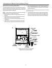
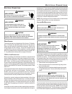
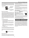
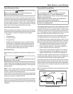
To use a single-stage thermostat, turn off power to the furnace,
move the thermostat selection DIP switch to the OFF position.
Set the desired transition time by setting the transition delay DIP
switch to the desired ON/OFF position. Turn power back on. Refer
to the following figure.
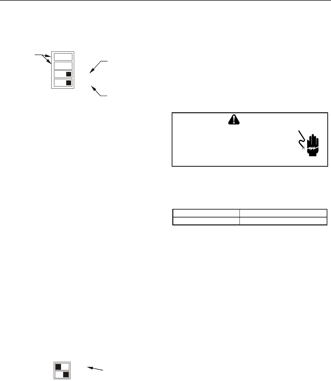
3
4
Thermostat
Stage Delay
Move to the ON position
to select two-stage
thermostat or OFF to
select single stage
thermostat
Move to the ON position
to select Auto transition
delay or OFF for 5 minute
transition delay
Heat OFF Delay
DIP Switches
ONOFF
S1
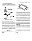
24 VOLT D EHUMIDISTAT W IRING
The optional usage of a dehumidistat allows the furnace’s circula-
tor blower to operate at a slightly lower speed (85% of desired
speed) during a combined thermostat call for cooling and dehumi-
distat call for dehumidification. This can be done through an inde-
pendent dehumidistat or through a thermostat’s DEHUM terminal
(if available). This lower blower speed enhances dehumidification
of the conditioned air as it passes through the AC coil. For proper
function, a dehumidistat applied to this furnace must operate on
24 VAC and utilize a switch which opens on humidity rise. Refer
to the “Thermostat Wiring Diagrams” figure for additional wir-
ing details.
To install/connect a dehumidistat:
1. Turn OFF power to furnace.
2. Secure the dehumidistat neutral wire (typically the white
lead) to the terminal marked “DEHUM” on the furnace
integrated control module.
3. Secure the dehumidistat hot wire (typically the black lead)
to the terminal marked “R” on the furnace integrated control
module.
4. Secure the dehumidistat ground wire (typically the green
lead) to the ground screw on the furnace junction box.
NOTE: Ground wire may not be present on all
dehumidistats.
5. Turn ON power to furnace.
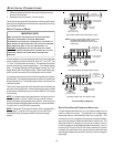
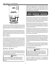
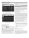
To enable the dehumidify function on the integrated control mod-
ule, set the dehumidification ENABLE dipswitch from OFF to ON.
Once the switch is set, the dehumidify function is enabled during a
combination call for cooling (T-Stat) and dehumidification (DEHUM-
Stat).
9
10
DEHUM
Unused
Move to the ON position
to enable dehumidification
ON
OFF
S5
FOSSIL F UEL A PPLICATIONS
This furnace can be used in conjunction with a heat pump in a
fossil fuel application. A fossil fuel application refers to a combined
gas furnace and heat pump installation which uses an outdoor
temperature sensor to determine the most cost efficient means of
heating (heat pump or gas furnace).
A heat pump thermostat with three stages of heat is required to
properly use a two-stage furnace in conjunction with a heat pump.
Refer to the fossil fuel kit installation instructions for additional
thermostat requirements.
Strictly follow the wiring guidelines in the fossil fuel kit installation
instructions. All furnace connections must be made to the furnace
two-stage integrated control module and the “FURNACE” terminal
strip on the fossil fuel control board.
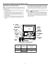
115 VOLT L INE C ONNECTION OF A CCESSORIES ( H UMIDIFIER AND
ELECTRONIC A IR C LEANER)
HIGHVOL TAGE!
T
O
AVOID
PERSONAL
INJURY
OR
DEATH
DUE
TO
ELECT RICAL
SHOCK
,
DISCONNECT
ELECT RICAL
POWER
BEFORE
SERVICING
OR
CHANGING
ANY
ELECT RICAL
WIRING
.
WARNING
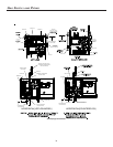
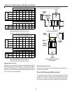
The furnace integrated control module is equipped with line voltage
accessory terminals for controlling power to an optional field-sup-
plied humidifier and/or electronic air cleaner.
The accessory load specifications are as follows:
Humidifier 1.0 Amp maximum at 120 VAC
Electronic Air Cleaner 1.0 Amp maximum at 120 VAC
Turn OFF power to the furnace before installing any accessories.
Follow the humidifier or air cleaner manufacturers’ instructions for
locating, mounting, grounding, and controlling these accessories.
Accessory wiring connections are to be made through the 1/4"
quick connect terminals provided on the furnace integrated control
module. The humidifier and electronic air cleaner hot terminals are
identified as HUM and EAC. The humidifier and electronic air
cleaner neutral terminals are identified as NEUTRAL. All field wir-
ing must conform to applicable codes. Connections should be
made as shown.