


49
T
ROUBLESHOOTING
& M
AINTENANCE
O
PERATIONAL
C
HECKS
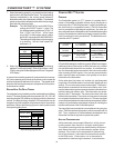
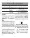
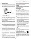
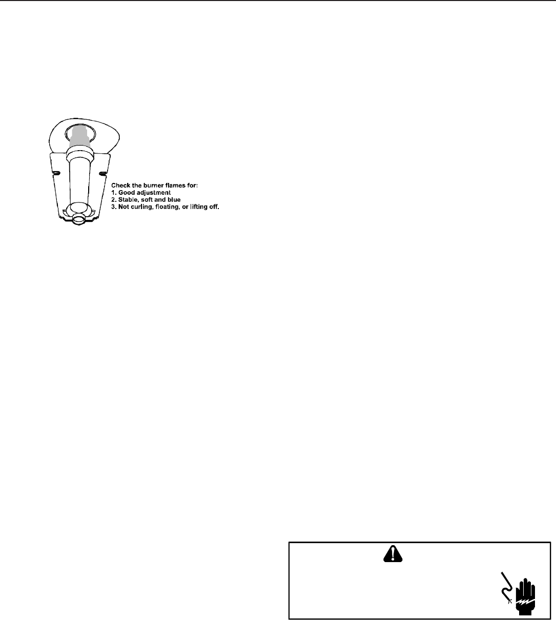
The burner flames should be inspected with the burner compart-
ment door installed. Flames should be stable, quiet, soft, and
blue (dust may cause orange tips but they must not be yellow).
Flames should extend directly outward from the burners without
curling, floating, or lifting off. Flames must not impinge on the
sides of the heat exchanger firing tubes.
Burner Flame
S
AFETY
C
IRCUIT
D
ESCRIPTION
A number of safety circuits are employed to ensure safe and proper
furnace operation. These circuits serve to control any potential
safety hazards and serve as inputs in the monitoring and diagno-
sis of abnormal function. These circuits are continuously moni-
tored during furnace operation by the integrated control module.
INTEGRATED C ONTROL M ODULE
The integrated control module is an electronic device which, if a
potential safety concern is detected, will take the necessary pre-
cautions and provide diagnostic information through an LED.
PRIMARY LIMIT
The primary limit control is located on the partition panel and moni-
tors heat exchanger compartment temperatures. It is a normally-
closed (electrically), automatic reset, temperature-activated sen-
sor. The limit guards against overheating as a result of insufficient
conditioned air passing over the heat exchanger.
AUXILIARY L IMIT
The auxiliary limit controls are located on or near the circulator
blower and monitors blower compartment temperatures. They are
a normally-closed (electrically), manual-reset sensors. These lim-
its guard against overheating as a result of insufficient conditioned
air passing over the heat exchanger.
ROLLOUT LIMIT
The rollout limit controls are mounted on the burner/manifold as-
sembly and monitor the burner flame. They are normally-closed
(electrically), manual-reset sensors. These limits guard against
burner flames not being properly drawn into the heat exchanger.
PRESSURE SWITCHES
The pressure switches are normally-open (closed during opera-
tion) negative air pressure-activated switches. They monitor the
airflow (combustion air and flue products) through the heat ex-
changer via pressure taps located on the induced draft blower and
the coil front cover. These switches guard against insufficient air-
flow (combustion air and flue products) through the heat exchanger
and/or blocked condensate drain conditions.
FLAME SENSOR
The flame sensor is a probe mounted to the burner/manifold as-
sembly which uses the principle of flame rectification to determine
the presence or absence of flame.
T
ROUBLESHOOTING
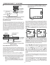
ELECTROSTATIC DISCHARGE (ESD) PRECAUTIONS
NOTE: Discharge body’s static electricity before touching unit.
An electrostatic discharge can adversely affect electrical
components.
Use the following precautions during furnace installation and ser-
vicing to protect the integrated control module from damage. By
putting the furnace, the control, and the person at the same elec-
trostatic potential, these steps will help avoid exposing the inte-
grated control module to electrostatic discharge. This procedure
is applicable to both installed and uninstalled (ungrounded) fur-
naces.
1. Disconnect all power to the furnace. Do not touch the
integrated control module or any wire connected to the
control prior to discharging your body’s electrostatic charge
to ground.
2. Firmly touch a clean, unpainted, metal surface of the furnace
away from the control. Any tools held in a person’s hand
during grounding will be discharged.
3. Service integrated control module or connecting wiring
following the discharge process in step 2. Use caution not
to recharge your body with static electricity; (i.e., do not
move or shuffle your feet, do not touch ungrounded objects,
etc.). If you come in contact with an ungrounded object,
repeat step 2 before touching control or wires.
4. Discharge your body to ground before removing a new
control from its container. Follow steps 1 through 3 if
installing the control on a furnace. Return any old or new
controls to their containers before touching any ungrounded
object.
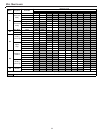
DIAGNOSTIC C HART
HIGHVOL TAGE!
T
O
AVOID
PERSONAL
INJURY
OR
DEATH
DUE
TO
ELECT RICAL
SHOCK
,
DISCONNECT
ELECT RICAL
POWER
BEFORE
PERFORMING
ANY
SERVICE
OR
MAINTENANCE
.
WARNING
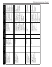
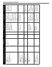
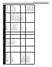
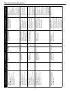
Refer to the Troubleshooting Chart in the Appendix for assistance
in determining the source of unit operational problems. The dual 7-
segment LED display will display an error code that may contain a
letter and number. The error code may be used to assist in trouble-
shooting the unit.