


40
S
TARTUP
P
ROCEDURE
& A
DJUSTMENT
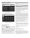
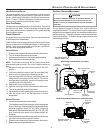
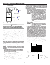
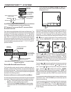
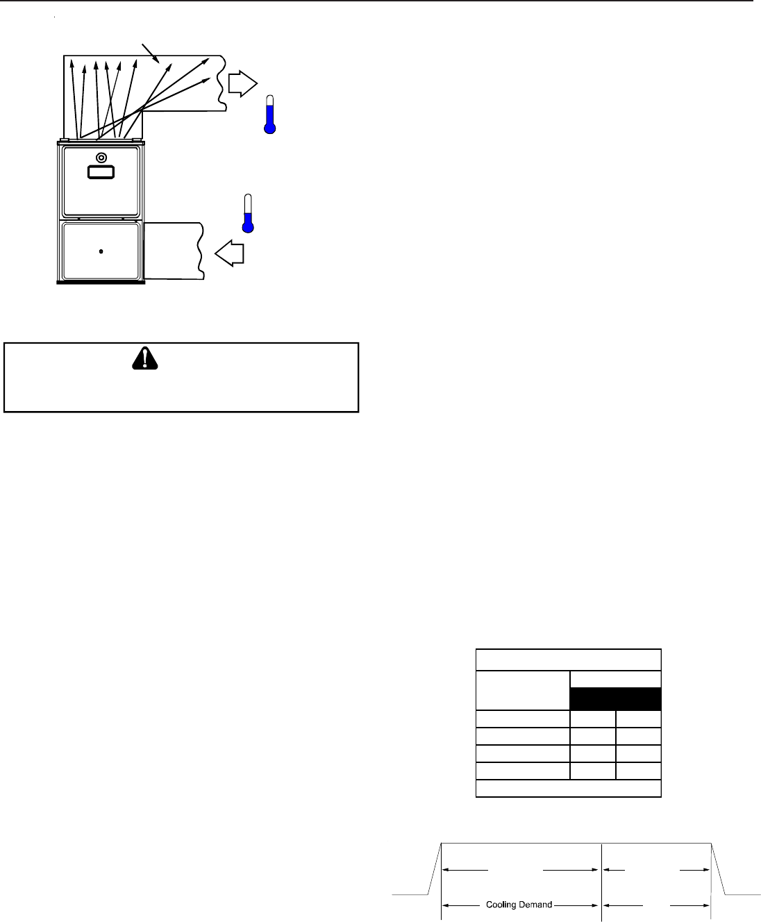
RISE =
SUPPLY
AIR
RETURN
AIR
HEAT EXCHANGER
RADIATION "LINE OF SIGHT"
T
RETURN
T
SUPPLY
T
SUPPLY
-
T
RETURN
Temperature Rise Measurement
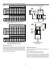
CIRCULATOR B LOWER S PEEDS
T
O
AVOID
PERSONAL
INJURY
OR
DEATH
DUE
TO
ELECT RICAL
SHOCK
,
TURN
OFF
POWER
TO
THE
FURNACE
BEFORE
CHANGING
SP EED
TAPS
.
WARNING
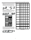
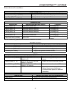
This furnace is equipped with a multi-speed circulator blower. This
blower provides ease in adjusting blower speeds. The Specifica-
tion Sheet applicable to your model provides an airflow table, show-
ing the relationship between airflow (CFM) and external static pres-
sure (E.S.P.), for the proper selection of heating and cooling speeds.
The heating blower speed is shipped set at “B”, and the cooling
blower speed is set at “D”. These blower speeds should be ad-
justed by the installer to match the installation requirements so as
to provide the correct heating temperature rise and correct cooling
CFM.
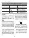
Use the dual 7-segment LED display adjacent to the dipswitches
to obtain the approximate airflow quantity. The airflow quantity is
displayed as a number on the display, rounded to the nearest 100
CFM. The display alternates airflow delivery indication and the
operating mode indication.
Example: The airflow being delivered is 1225 CFM. The display
indicates 12. If the airflow being delivered is 1275, the display
indicates 13.
1. Determine the tonnage of the cooling system installed with
the furnace. If the cooling capacity is in BTU/hr divide it by
12,000 to convert capacity to TONs.
Example: Cooling Capacity of 30,000 BTU/hr.
30,000/12,000 = 2.5 Tons
2. Determine the proper air flow for the cooling system. Most
cooling systems are designed to work with air flows between
350 and 450 CFM per ton. Most manufacturers recommend
an air flow of about 400 CFM per ton.
Example: 2.5 tons X 400 CFM per ton = 1000 CFM
The cooling system manufacturer’s instructions must be checked
for required air flow. Any electronic air cleaners or other devices
may require specific air flows, consult installation instructions of
those devices for requirements.
3. Knowing the furnace model, locate the high stage cooling
air flow charts in the Specification Sheet applicable to your
model. Look up the cooling air flow determined in step 2
and find the required cooling speed and adjustment setting.
Example: A *MVC95704CX furnace installed with a 2.5
ton air conditioning system. The air flow
needed is 1000 CFM. Looking at the cooling
speed chart for *MVC95704CX, find the air
flow closest to 1000 CFM. A cooling airflow
of 990 CFM can be attained by setting the
cooling speed to “C” and the adjustment to “-
” (minus).
4. Continuous fan speed is 30% of the furnace’s maximum
airflow capability.
Example: If the furnace’s maximum airflow capability is
2000 CFM, the continuous fan speed will be
0.30 x 2000 CFM = 600 CFM.
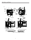
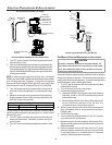
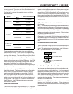
5. Locate the blower speed selection DIP switches on the
integrated control module. Select the desired “cooling”
speed tap by positioning switches 1 and 2 appropriately.
Select the desired “adjust” tap by positioning switches 3
and 4 appropriately. Refer to the following figure for switch
positions and their corresponding taps. Verify CFM by noting
the number displayed on the dual 7-segment LED display.
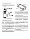
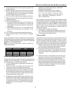
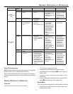
6. The multi-speed circulator blower also offers several custom
ON/OFF ramping profiles. These profiles may be used to
enhance cooling performance and increase comfort level.
The ramping profiles are selected using DIP switches 5
and 6. Refer to the following figure for switch positions and
their corresponding taps. Refer to the bullet points below
for a description of each ramping profile. Verify CFM by
noting the number displayed on the dual 7-segment LED
display.
56
A* OFF OFF
BONOFF
COFFON
DONON
Switch Bank: S4
DIP Sw itch No.
(*Indicates factory setting)
Ramping
Profiles
• Profile A provides only an OFF delay of one (1) minute at
100% of the cooling demand airflow.
OFF
100% CFM 100% CFM
1 min
OFF