


14
V
ENT
/F
LUE
P
IPE
& C
OMBUSTION
A
IR
P
IPE
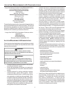
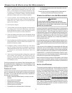
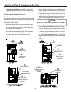
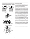
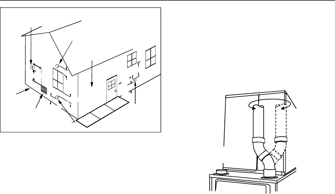
vicing. Combustion Air and Vent piping should be routed in a man-
ner to avoid contact with refrigerant lines, metering devices, con-
densate drain lines, etc. If necessary, clearances may be in-
creased by utilizing two 45 deg. Long-Sweep Elbows and creat-
ing an “S” joint to provide additional space at connection loca-
tions. This joint can be rotated on the fitting to establish maxi-
mum clearance between refrigerant lines, metering devices, and
condensate drain lines, etc. This joint is the equivalent of one 90
deg. elbow when considering elbow count.
45 DEGREE
LONG-SWEEP
ELBOWS
V
E
N
T
Increased Clearance Configuration
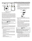
NOTE: Do not use other commercially available “no hub connec-
tors” due to possible material conflicts. The vent/flue pipe can also
be secured using a PVC or ABS elbow or coupling using the
appropriate glue (see Materials and Joining Methods).
NOTE: For non-direct vent installations, a minimum of one 90°
elbow should be installed on the combustion air intake coupling to
guard against inadvertent blockage.
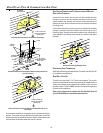
COMBUSTION AIR PIPE
DIRECT VENT I NSTALLATIONS
On upflow units secure the combustion air intake pipe directly to
the air intake coupling. On counterflow units secure the combus-
tion air intake pipe to the air intake coupling using the rubber cou-
pling and worm gear hose clamps provided with the unit. The coun-
terflow rubber coupling allows service removal of air intake piping
internal to the furnace blower compartment. NOTE: Because of
probable material conflicts, do not use other commercially avail-
able “no hub connectors”. The combustion air intake pipe can
also be secured directly to the counterflow unit air intake pipe
coupling.
NON-DIRECT VENT I NSTALLATIONS
A minimum of one 90° elbow should be installed on the combus-
tion air intake “coupling” to guard against inadvertent blockage.
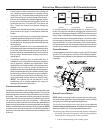
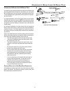
Vent Termination Clearances
NOTE: In Canada, the Canadian Fuel Gas Code takes precedence
over the preceding termination restrictions.
CANADIAN V ENTING R EQUIREMENTS
In Canada, venting must conform to the requirements of the cur-
rent CAN/CSA-B149.1-05 Installation Code. Use only CSA-listed,
ULC-S636 compliant two- or three-inch diameter PVC or ABS pipe,
solvent cement, and fittings throughout. The certified piping should
be clearly marked with the ULC Std “S636” on the pipe and fittings.
Carefully follow the pipe manufacturers’ instructions for cutting,
cleaning, and solvent cementing PVC and/or ABS.
The vent can be run through an existing unused chimney provided
the space between the vent pipe and the chimney is insulated and
closed with a weather-tight, corrosion-resistant flashing.
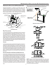
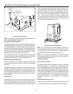
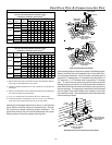
STANDARD F URNACE C ONNECTIONS
It is the responsibility of the installer to ensure that the piping
connections to the furnace are secure, airtight, and adequately
supported.
As shipped, attachment “couplings” for vent/flue and combustion
air intake pipe connections are provided on the furnace’s top cover
(upflow) or basepan (counterflow). To use the standard connec-
tions, field supplied vent/flue pipe and combustion air intake pipe
(when applicable) should be secured directly to the furnace at
these locations.
VENT/FLUE P IPE
Vent/flue pipe can be secured to the vent/flue coupling using the
rubber coupling and worm gear hose clamps provided with this
furnace (see “Standard Connections” figure). The rubber coupling
allows separation of the vent/flue pipe from the furnace during ser-
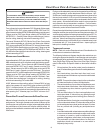
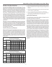
12"
Non-Direct Vent
Vent/Flue Termination
No Terminations
Above Walkway
12"
min.
4'
min.
Non-Direct Vent
Vent/Flue Termination
Direct Vent
Vent/Flue Termination
<10'
Forced Air
Inlet
Non-Direct Vent
&
Direct Vent
Vent/Flue Terminations
Grade or Highest
Anticipated
Snow Level
3' min.
12" min.
4' min.
12" min.