


17
V
ENT
/F
LUE
P
IPE
& C
OMBUSTION
A
IR
P
IPE
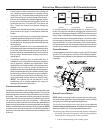
NON-DIRECT V ENT (SINGLE P IPE) PIPING
Non-direct vent installations require only a vent/flue pipe. The vent
pipe can be run horizontally with an exit through the side of the
building or run vertically with an exit through the roof of the building.
The vent can also be run through an existing unused chimney;
however, it must extend a minimum of 12 inches above the top of
the chimney. The space between the vent pipe and the chimney
must be closed with a weather-tight, corrosion-resistant flashing.
For details concerning connection of the vent/flue pipe to the fur-
nace, refer to Vent/Flue Pipe and Combustion Air - Standard Fur-
nace Connections or Alternate Furnace Connections for specific
details. Refer to the following Non-Direct Vent (Single Pipe) Piping
- Vent/Flue Pipe Terminations for specific details on termination
construction.
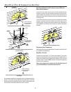
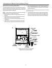
Although non-direct vent installations do not require a combustion
air intake pipe, a minimum of one 90° elbow should be attached to
the furnace’s combustion air intake if: an upright installation uses
the standard intake location, or a horizontal installation uses the
alternate air intake location. This elbow will guard against inadvert-
ent blockage of the air intake.
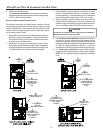
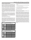
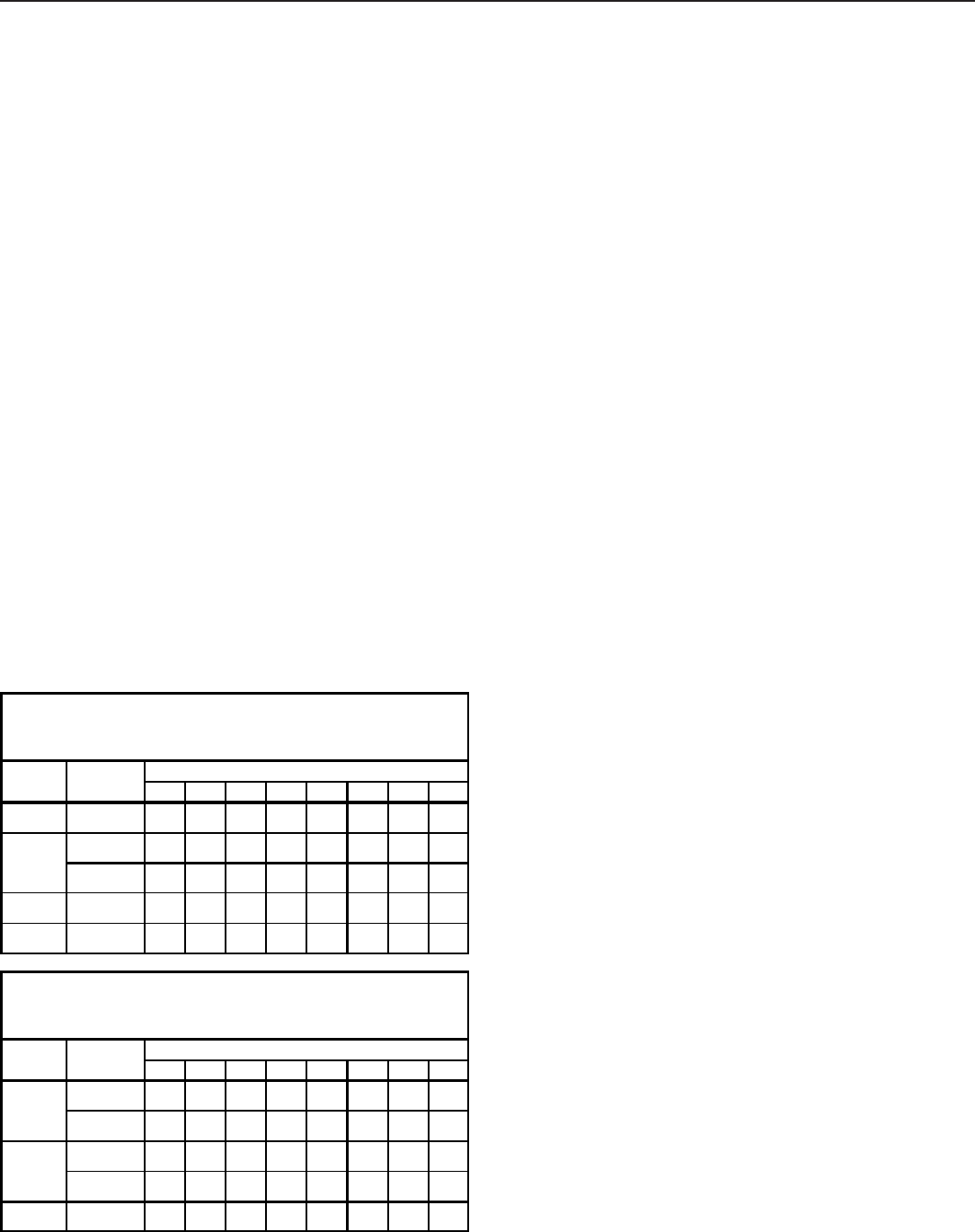
VENT/FLUE P IPE L ENGTHS AND DIAMETERS
Refer to the following table for applicable length, elbows, and pipe
diameter for construction of the vent/flue pipe system of a non-
direct vent installation. In addition to the vent/flue pipe, a single 90°
elbow should be secured to the combustion air intake to prevent
inadvertent blockage. The tee used in the vent/flue termination
must be included when determining the number of elbows in the
piping system.
12345678
45,0002 or 2 1/27168656259565350
2 or 2 1/24946434037343128
3 7168656259565350
90,000 3 7168656259565350
115,000 3 4946434037343128
12345678
2 or 2 1/26158555249464340
3 7168656259565350
2 or 2 1/26158555249464340
3 7168656259565350
115,000 3 7168656259565350
UPFLOW
Non-Direct Vent (Single Pipe)
Maximum Allowable Length of Vent/Flue Pipe (ft)
(1)(2)
70,000
Number of Elbows
(3)(5)
Pipe
(4)
(Inch)
Unit
Input
70,000
90,000
COUNTERFLOW
Non-Direct Vent (Single Pipe)
Maximum Allowable Length of Vent/Flue Pipe (ft)
(1)(2)
Unit
Input
Pipe
(4)
(Inch)
Number of Elbows
(3)(5)
1) One 90° elbow should be secured to the combustion air intake connection.
2) Minimum requirement for each vent pipe is five (5) feet in length and one
elbow/tee.
3) Tee used in the vent/flue termination must be included when determining the
number of elbows in the piping system.
4) 2-1/2” or 3” diameter pipe can be used in place of 2” diameter pipe.
5) Increased Clearance Configurations using (2) 45 deg.
Long Sweep el-
bows should be considered equivalent to one 90 deg. elbow.
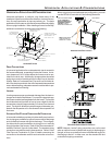
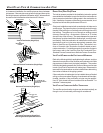
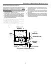
VENT/FLUE P IPE T ERMINATIONS
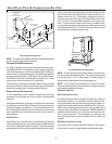
The vent/flue pipe may terminate vertically, as through a roof, or
horizontally, as through an outside wall.
Vertical vent/flue pipe terminations should be as shown in the fol-
lowing figure. Refer to Vent/Flue Pipe and Combustion Air Pipe -
Termination Locations for details concerning location restrictions.
The penetration of the vent through the roof must be sealed tight
with proper flashing such as is used with a plastic plumbing vent.
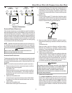
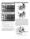
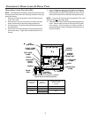
Horizontal vent/flue pipe terminations should be as shown in the
following figure. Refer to Vent/Flue Pipe and Combustion Air Pipe
- Termination Locations for details concerning location restrictions.
A 2 3/8” diameter wall penetration is required for 2” diameter pipe.
A 3” diameter hole is required for a 2 1/2” pipe and a 3 1/2” diam-
eter hole is required for 3” diameter pipe. To secure the pipe pass-
ing through the wall and prohibit damage to piping connections, a
coupling should be installed on either side of the wall and solvent
cemented to a length of pipe connecting the two couplings. The
length of pipe should be the wall thickness plus the depth of the
socket fittings to be installed on the inside and outside of the wall.
The wall penetration should be sealed with silicone caulking
material.