


33
G
AS
S
UPPLY
AND
P
IPING
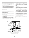
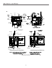
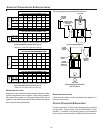
DIRECT/STANDARD INLET P IPING
E
DGES
OF
SHEET
METAL
HOLES
MAY
BE
SHARP
.U
SE
GLOVES
AS
A
PRECAUTION
WHEN
REMOVING
HOLE
PLUGS
.
WARNING
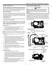
When gas piping enters directly to the gas valve through the stan-
dard inlet hole, the installer must supply straight pipe with a ground
joint union to reach the exterior of the furnace. The rigid pipe must
be long enough to reach the outside of the cabinet to seal the
grommet cabinet penetration. A semi-rigid connector to the gas
piping can be used outside the cabinet per local codes.
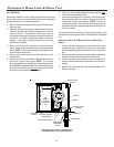
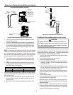
INDIRECT/ALTERNATE I NLET P IPING
When gas piping enters indirectly to the gas valve through the
alternate gas inlet hole the following fittings (starting from the gas
valve) to reach the outside of the cabinet must be supplied:
• Coupling.
• 90 degree elbow.
• 2 inch close nipple.
• 90 degree elbow.
• Straight pipe, with a ground joint union, to reach the exterior
of the furnace. The rigid pipe must be long enough to reach
the outside of the cabinet so as to seal the grommet cabinet
penetration. A semi-rigid connector to the gas piping can
be used outside the cabinet per local codes.
GAS PIPING CHECKS
Before placing unit in operation, leak test the unit and gas connec-
tions.
T
O
AVOID
THE
POSSIBILITY
OF
EXPLOSION
OR
FIRE
,
NEVER
USE
A
MATCH
OR
OPEN
FLAME
TO
TEST
FOR
LEA KS
.
WARNING
Check for leaks using an approved chloride-free soap and water
solution, an electronic combustible gas detector, or other approved
testing methods.
NOTE: Never exceed specified pressures for testing. Higher
pressure may damage the gas valve and cause subsequent
overfiring, resulting in heat exchanger failure.
Disconnect this unit and shutoff valve from the gas supply piping
system before pressure testing the supply piping system with
pressures in excess of 1/2 psig (3.48 kPa).
Isolate this unit from the gas supply piping system by closing its
external manual gas shutoff valve before pressure testing supply
piping system with test pressures equal to or less than 1/2 psig
(3.48 kPA).
PROPANE G AS T ANKS AND P IPING
I
F
THE
GAS
FURNACE
IS
INSTALLED
IN
A
BASEMENT
,
AN
EXCAVATED
AREA
OR
CONFINED
SPACE
,
IT
IS
STRONGLY
RECOMMENDED
TO
CONTACT
A
PROPANE
SUPPLIER
TO
INSTALL
A
GAS
DETECTING
WARNING
DEVICE
IN
CASE
OF
A
GAS
LEA K
.
S
INCE
PROPANE
GAS
IS
HEAVIER
THAN
AIR
,
ANY
LEAKING
GAS
CAN
SETTLE
IN
ANY
LOW
AREAS
OR
CONFINED
SPACES
.
P
ROPANE
GAS
ODORANT
MAY
FADE
,
MAKING
THE
GAS
UNDETECTABLE
EXCEPT
WITH
A
WARNING
DEVICE
.
•
•
WARNING
A gas detecting warning system is the only reliable way to detect
a propane gas leak. Rust can reduce the level of odorant in pro-
pane gas. Do not rely on your sense of smell. Contact a local
propane gas supplier about installing a gas detecting warning sys-
tem. If the presence of gas is suspected, follow the instructions
listed in the Safety Precautions section of this manual.
All propane gas equipment must conform to the safety standards
of the National Board of Fire Underwriters, NBFU Manual 58.
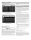
For satisfactory operation, propane gas pressure must be 11 inch
WC at the furnace manifold with all gas appliances in operation.
Maintaining proper gas pressure depends on three main factors:
1. Vaporization rate, depending on temperature of the liquid,
and “wetted surface” area of the container or containers.
2. Proper pressure regulation. (Two-stage regulation is
recommended for both cost and efficiency).
3. Pressure drop in lines between regulators, and between
second stage regulator and the appliance. Pipe size will
depend on length of pipe run and total load of all appliances.
Complete information regarding tank sizing for vaporization, rec-
ommended regulator settings, and pipe sizing is available from
most regulator manufacturers and propane gas suppliers.
Since propane gas will quickly dissolve white lead and most stan-
dard commercial compounds, special pipe dope must be used.
Shellac-based compounds resistant to the actions of liquefied pe-
troleum gases such as Gasolac®, Stalactic®, Clyde’s® or John
Crane® are satisfactory.
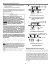
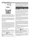
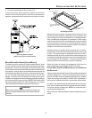
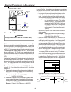
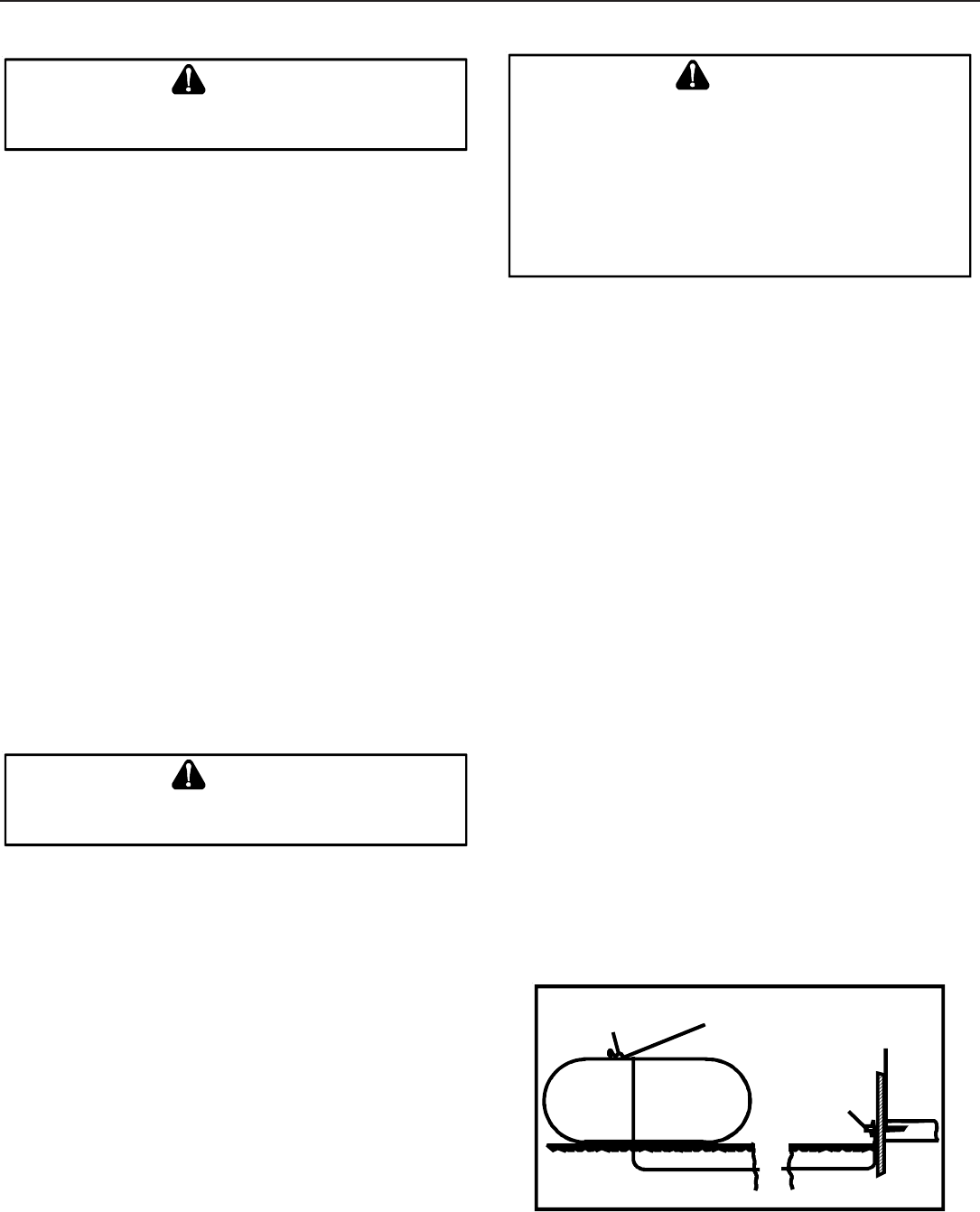
Refer to the following illustration for typical propane gas installa-
tions and piping.
200 PSIG
Maximum
5 to 15 PSIG
(20 PSIG Max.)
Continuous
11" W.C.
Second Stage
Regulator
First Stage
Regulator
Propane Gas Installation (Typ.)