


39
S
TARTUP
P
ROCEDURE
& A
DJUSTMENT
9. Close thermostat “R” and “W2” contacts to provide a call
for high stage heat.
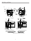
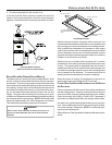
10. Remove regulator cover screw from the high (HI) outlet
pressure regulator adjust tower and turn screw clockwise
to increase pressure or counterclockwise to decrease
pressure. Replace regulator cover screw.
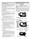
11. Turn off all electrical power and gas supply to the system.
12. Remove the manometer hose from the hose barb fitting or
outlet pressure boss.
13. Replace outlet pressure tap:
a. Honeywell VR9205 valve: Remove the 1/8" NPT hose
barb fitting from the outlet pressure tap. Replace the
outlet pressure boss plug and seal with a high quality
thread sealer.
b. White-Rodgers 36G54 valve: Turn outlet pressure test
screw in to seal pressure port (clockwise, 7 in-lb
minimum).
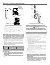
14. Turn on electrical power and gas supply to the system.
15. Close thermostat contacts “R” and “W1/W2” to energize
the valve.
Using a leak detection solution or soap suds, check for leaks at
outlet pressure boss plug (Honeywell valve) or screw (White-Rodg-
ers valve). Bubbles forming indicate a leak. SHUT OFF GAS AND
REPAIR ALL LEAKS IMMEDIATELY!
NOTE: For gas to gas conversion, consult your dealer for
appropriate conversion.
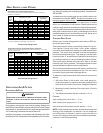
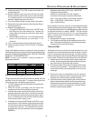
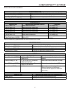
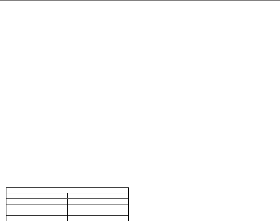
Range Nominal
Natural Low Stage 1.6 - 2.2" w .c. 1.9" w .c.
High Stage 3.2 - 3.8" w .c. 3.5" w .c.
Propane Low Stage 5.7 - 6.3" w .c. 6.0" w .c.
High Stage 9.7 - 10.3" w .c
.
10.0" w.c.
Manifold Gas Pressure
Gas
GAS I NPUT R ATE M EASUREMENT (NATURAL G AS O NLY)
The gas input rate to the furnace must never be greater than that
specified on the unit rating plate. To measure natural gas input
using the gas meter, use the following procedure.
1. Turn OFF the gas supply to all other gas-burning appliances
except the furnace.
2. While the furnace is operating, time and record one
complete revolution of the smallest gas meter dial.
3. Calculate the number of seconds per cubic foot (sec/ft
3
) of
gas being delivered to the furnace. If the dial is a one cubic
foot dial, divide the number of seconds recorded in step 2
by one. If the dial is a two cubic foot dial, divide the number
of seconds recorded in step 2 by two.
4. Calculate the furnace input in BTUs per hour (BTU/hr). Input
equals the sum of the installation’s gas heating value and a
conversion factor (hours to seconds) divided by the number
of seconds per cubic foot. The measured input must not
be greater than the input indicated on the unit rating plate.
EXAMPLE:
Installation’s gas heating (HTG) value: 1,000 BTU/ft
3
(Obtained from gas supplier)
Installation’s seconds per cubic foot: 34 sec/ ft
3
Conversion Factor (hours to seconds): 3600 sec/hr
Input = (Htg. value x 3600) ÷ seconds per cubic foot
Input = (1,000 BTU/ft
3
x 3600 sec/hr) ÷ 34 sec/ ft
3
Input = 106,000 BTU/hr
Minor changes to the input rate may be accomplished through
manifold pressure adjustments at the gas valve. Refer to Startup
Procedure and Adjustment - Gas Manifold Pressure Measurement
and Adjustment section for details. NOTE: The final manifold
pressure cannot vary by more than ± 0.3” w.c. from the specified
setting. Consult your local gas supplier if additional input rate
adjustment is required.
5. Repeat steps 2 through 4 on high stage.
6. Turn ON gas to and relight all other appliances turned off in
step 1. Be certain that all appliances are functioning properly
and that all pilot burners are operating.
TEMPERATURE R ISE
Temperature rise must be within the range specified on the unit
rating plate. An incorrect temperature rise may result in condens-
ing in or overheating of the heat exchanger. An airflow and tem-
perature rise table is provided in the Specification Sheet applicable
to your model. Determine and adjust temperature rise as follows:
1. Operate furnace with burners firing for approximately ten
minutes. Ensure all registers are open and all duct dampers
are in their final (fully or partially open) position.
2. Place thermometers in the return and supply ducts as close
to the furnace as possible. Thermometers must not be
influenced by radiant heat by being able to “see” the heat
exchanger.
3. Subtract the return air temperature from the supply air
temperature to determine the air temperature rise. Allow
adequate time for thermometer readings to stabilize.
4. Adjust temperature rise by adjusting the circulator blower
speed. Increase blower speed to reduce temperature rise.
Decrease blower speed to increase temperature rise. Refer
to Startup Procedure and Adjustment -Circulator Blower
Speeds for speed changing details.