


24
C
ONDENSATE
D
RAIN
L
INES
& D
RAIN
T
RAP
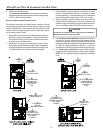
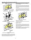
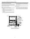
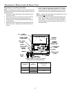
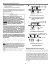
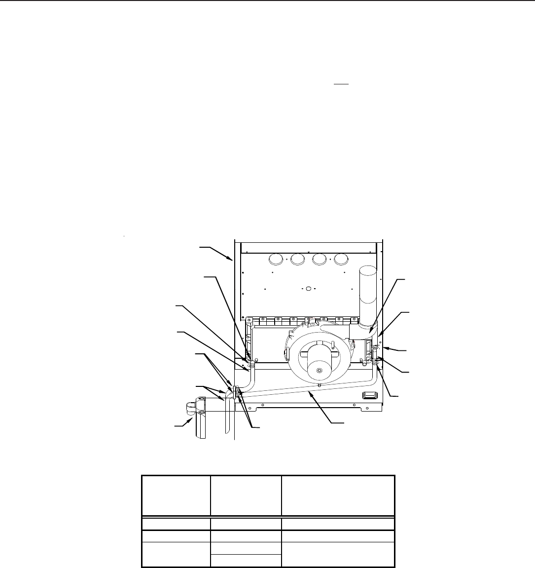
UPRIGHT I NSTALLATIONS-TRAP ON L EFT S IDE
NOTE: For left side trap installation, grommets must be moved
to the left side of the furnace and the plugs installed on the right
side of the furnace.
1. Remove the rubber plug/cap from the left side drain port
on the front cover.
2. Secure Hose A to front cover drain port with a red hose
clamp. Route hose to rear side panel grommet hole.
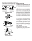
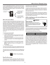
3. Cut and remove 1/4 inch from the end of the drain port on
the rubber elbow.
4. Insert Tube 1 into rubber elbow drain port and secure with
silver hose clamp. Angle tube outward toward front of
furnace.
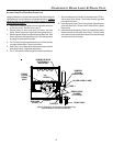
5. Cut “X” inches from the long end of Hose B and discard.
Refer to table for appropriate length to cut. Secure
remaining hose to Tube 1 with a green hose clamp. Route
other end of Hose B to front left side panel grommet hole.
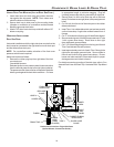
NOTE: Long hose “B” must always be connected to Tube 1 and
the elbow and
not on the front cover.
6. Insert short end of each Tube 2 through side panel grommet
holes. Secure tubes to Hose A and Hose B with green
hose clamps. Ensure hoses and tubes maintain a
downward slope for proper drainage and that they are not
kinked or binding.
LEFT
SIDE PANEL
FRONT COVER
DRAIN PORT
HOSE A
SIDE PANEL
DRAIN
HOLES
TUBE(S) 2
DRAIN
TRAP
GREEN HOSE
CLAMP
TUBE 1
RUBBER
ELBOW
HOSE B
RUBBER
ELBOW
DRAIN PORT
RED HOSE
CLAMP
SILVER HOSE
CLAMP
GREEN
HOSE CLAMP
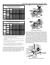
Upright “Standard” Connections - Left Side
(Upflow Shown, Counterflow Similar)
Cabinet Width
(inches)
Models
(kBTU_Tons)
"X" Length to Cut From Long
End of Hose B
(inches)
17 1/2 45_30 7
21 70_40 3 1/2
090_50
115_50
None24 1/2