


15
V
ENT
/F
LUE
P
IPE
& C
OMBUSTION
A
IR
P
IPE
RUBBER
COUPLING
WITH WORM
GEAR CLAMPS
RUBBER
COUPLINGS
WITH WORM
GEAR CLAMPS
COMBUSTION
AIR PIPE
(DIRECT VENT ONLY)
COMBUSTION
AIR PIPE
(DIRECT VENT ONLY)
VENT/FLUE
PIPE
VENT/FLUE
PIPE
90 PVC
ELBOW
(
NON-DIRECT VENT
)
90 PVC
ELBOW
(
NON-DIRECT VENT
)
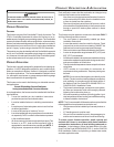
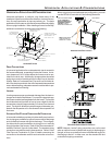
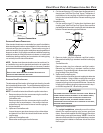
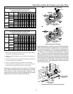
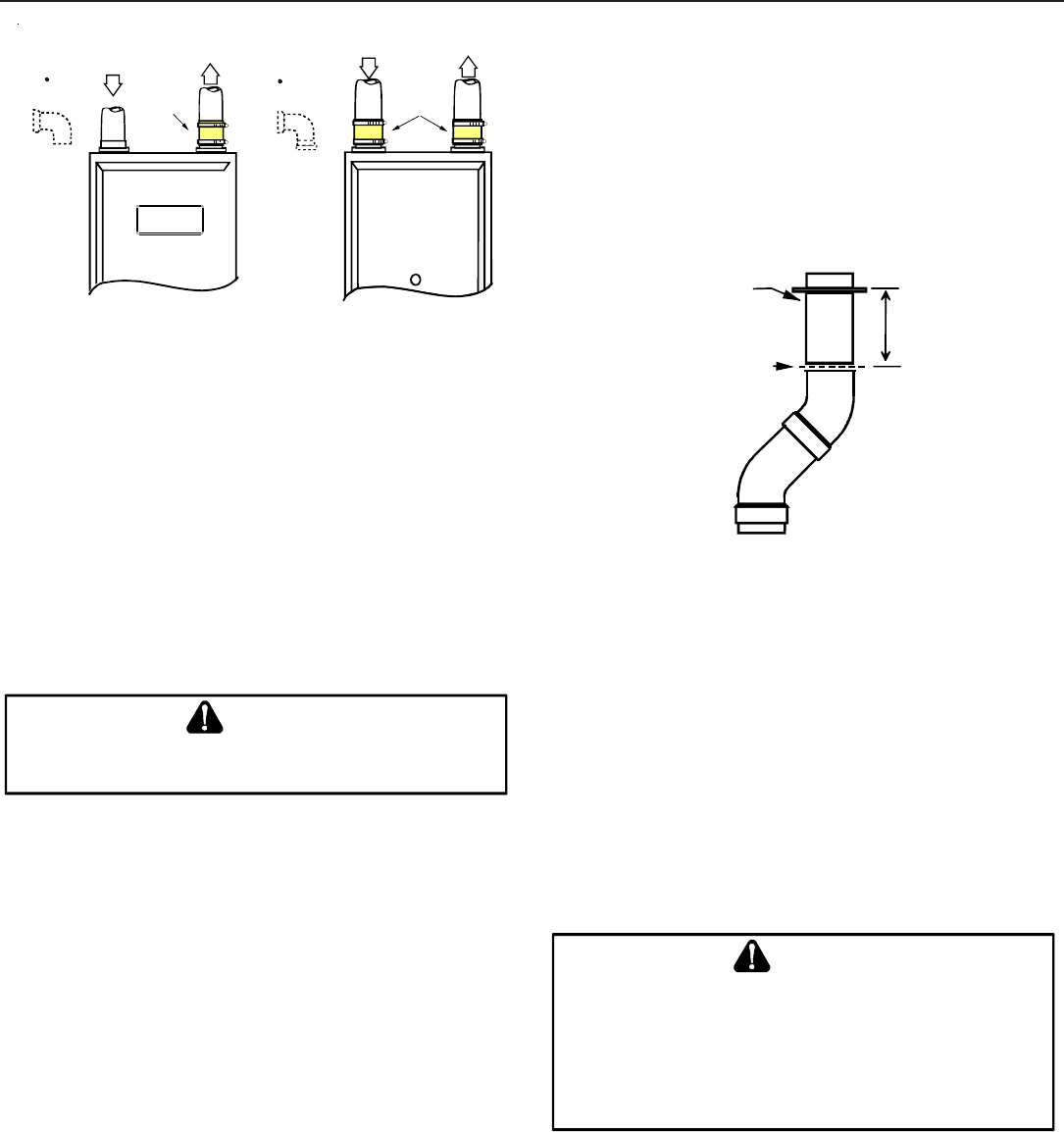
Standard Connections
OR
OR
UPFLOW COUNTERFLOW
ALTERNATE F URNACE C ONNECTIONS
If the standard locations are undesirable for a specific installation,
alternate side panel locations are available for both combustion air
inlet and vent/flue pipe connections. These locations may be of
particular benefit to upright upflow installations requiring additional
access to an A coil, or to upright counterflow installations requiring
additional access to a filter or electronic air cleaner, or to horizontal
installations desiring vent/flue (and combustion air intake) piping
run vertically from the side of the cabinet.
NOTE: Standard and alternate locations can be combined (i.e.,
an installation may use the standard combustion air intake loca-
tion but use the alternate vent/flue location or vice versa), if needed.
E
DGES
OF
SHEET
METAL
HOLES
MAY
BE
SHARP
.U
SE
GLOVES
AS
A
PRECAUTION
WHEN
REMOVING
HOLE
PLUGS
.
WARNING
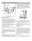
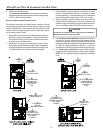
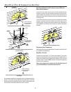
ALTERNATE V ENT/FLUE L OCATION
The alternate vent/flue location is the large hole directly in line with
the induced draft blower outlet. To use the alternate vent/flue loca-
tion refer to the following steps and the “Alternate Vent/Flue Loca-
tion” figure.
NOTE: Counterflow instructions follow the upflow instructions.
1. Remove and save the four screws securing the vent/flue
coupling to the furnace top panel.
Counterflow units.
Remove and save the four screws securing the vent/flue
coupling to the furnace basepan. Also remove the three
screws securing the furnace’s internal vent/flue piping to
the blower deck.
2. Upflow and Counterflow units.
Loosen the worm gear hose clamps on the rubber elbow
and detach it from both the induced draft blower and the
vent/flue pipe.
3. Upflow and Counterflow units.
Remove the vent/flue pipe from the furnace.
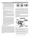
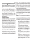
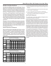
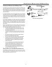
4. Cut the vent/flue pipe 3.75 inches from the flanged end of
the pipe (see “Vent/Flue Pipe Cuts” figure). The section of
pipe attached to the coupling will reach through the side
panel to the induced draft blower. Discard remaining pipe
and elbows.
Counterflow units.
Cut the vent/flue pipe 3.75 inches from the blower deck
coupling (see “Vent/Flue Pipe Cuts” figure). Save vent/flue
pipe attached to blower deck coupling for use in the alternate
location. Discard remaining pipe and elbows.
FLANGE
CUT
HERE
3.75"
Vent/Flue Pipe Cuts
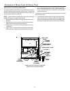
5. Remove plastic plug from alternate vent/flue location.
Relocate and install plug in standard vent/flue location (top
cover).
Counterflow units.
Remove plastic plug from alternate vent/flue location.
Relocate and install plug in standard vent/flue location
(basepan). Plug remaining hole in blower deck with plastic
plug included in the drain kit bag.
6. Upflow and Counterflow units.
Insert cut section of vent/flue pipe and coupling into alternate
vent/flue location. Using a rubber coupling and worm gear
hose clamps from the drain kit bag, attach the vent/flue
pipe and coupling to the induced draft blower. Secure the
coupling to the cabinet using the screws removed in step 1
or with field-supplied 3/8” #8 self drilling screws.
T
HE
RUBBER
ELBOW
IS
NOT
DESIGNED
TO
SUPPORT
A
LOAD
.W
HEN
THE
RUBBER
ELBOW
IS
MOUNTED
EXTERNALLY
TO
THE
FURNACE
CABINET
,
EXTREME
CARE
MUST
BE
TAKEN
TO
ADEQUATELY
SUPPORT
FIELD
‐
SUPPLIED
VENT
/
FLUE
PIPING
,
AS
DAMAGE
CAN
RESULT
IN
LEA KS
CAUSING
BODILY
INJURY
OR
DEATH
DUE
TO
EXPOSURE
TO
FLUE
GASES
,
INCLUDING
CARBON
MONOXIDE
WARNING
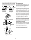
7. Upflow and Counterflow units.
For upright installations, externally mount the rubber
elbow to the vent/flue coupling using a worm gear hose
clamp. Secure field supplied vent/flue piping to the rubber
elbow using a worm gear hose clamp. NOTE: Use of the
alternate vent/flue location for upright installations, requires
the drain trap be installed on the same side of the unit as
the flue pipe.