


16
V
ENT
/F
LUE
P
IPE
& C
OMBUSTION
A
IR
P
IPE
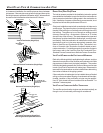
8. Upflow and Counterflow units.
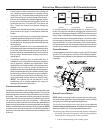
For horizontal installations, externally secure the field-
supplied vent/flue pipe directly to the vent/flue coupling using
a PVC or ABS coupling or elbow.
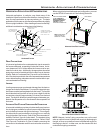
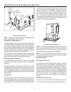
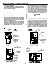
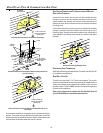
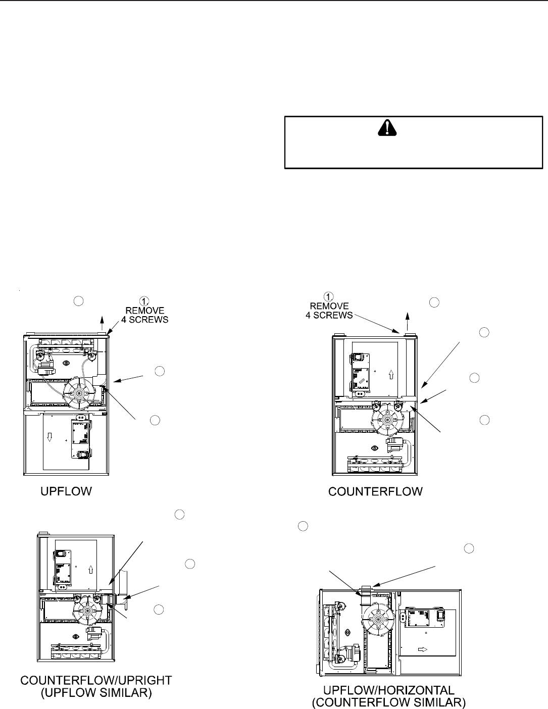
ALTERNATE COMBUSTION AIR INTAKE LOCATION
The alternate combustion air intake location consists of a large,
unobstructed hole (alternate vent connection is aligned with the
Induced Draft Blower). To use the alternate combustion air intake
location, refer to the following steps, and the “Alternate Combus-
tion Air Intake Location” figure.
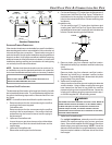
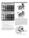
1. Remove and save the four screws securing the combustion
air intake coupling to the basepan. Remove an additional
three screws securing the furnace’s internal combustion
air intake pipe to the blower deck.
2. Remove the combustion air intake pipe from the furnace
and cut the pipe at the basepan coupling. Save the basepan
coupling and gasket from the blower deck coupling for use
in the alternate location. Discard the remaining pipe.
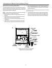
3. Remove plastic plug from alternate combustion air intake
location. Relocate and install plug in standard air intake
location (basepan). Plug the remaining hole in the blower
deck with the plastic plug included in the drain kit bag.
4. With the gasket facing the cabinet side panel, and the
flange’s flat spot facing forward, secure the combustion air
intake coupling to the cabinet using the screws removed in
step 1 or with field-supplied 3/8” #8 self -drilling screws.
B
E
SURE
NOT
TO
DAMAGE
INTERNAL
WIRING
OR
OTHER
COMPONENTS
WHEN
REINSTALLING
COUPLING
AND
SCREWS
.
CAUTION
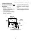
5. For non-direct vent installations installed horizontally, a
minimum of one 90° elbow should be installed on the
combustion air intake coupling to guard against inadvertent
blockage. No elbow is required on the alternate combustion
air intake of upright installations, however, a minimum
clearance of 2 inches is required to assure proper air supply.
6. For direct vent installations, secure field-supplied
combustion air intake pipe directly to the air intake coupling.
NOTE: A PVC coupling or elbow is required on counterflow
units.
5
ADDITIONAL PLUG
FROM DRAIN KIT
7
EXTERNALLY
MOUNT
RUBBER ELBOW
6
SECURE TO
ID BLOWER WITH
RUBBER COUPLING
AND HOSE
CLAMPS
3
REMOVE
PIPE
2
DETACH RUBBER
ELBOW FROM
ID BLOWER AND
VENT/FLUE
PIPE
2
DETATCH RUBBER
ELBOW FROM
ID BLOWER AND
VENT/FLUE
PIPE
3
REMOVE
PIPE
5
REMOVE
A
ND RELOCATE
5
REMOVE
AND RELOCATE
1
REMOVE
3 SCREWS
6
SECURE TO
ID BLOWER WITH
RUBBER COUPLING
AND HOSE
CLAMPS
6
SECURE TO
CABINET WITH
SCREWS