


23
C
ONDENSATE
D
RAIN
L
INES
& D
RAIN
T
RAP
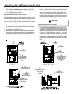
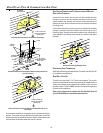
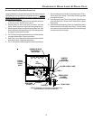
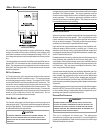
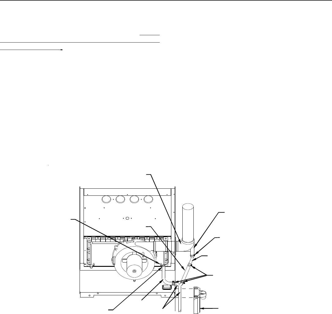
ALTERNATE V ENT/FLUE D RAIN H OSE C ONNECTIONS
Upright installations using the alternate vent/flue outlet will require
“right-side only” drain hoses to be connected as follows. Refer to
Vent/Flue Pipe and Combustion Air Pipe for details on alternate
vent/flue pipe connection.
1. Remove the rubber plug/cap from the right-side drain port
on the front cover . Save for use in step 3.
2. Secure Hose A to front cover drain port with a red hose
clamp. Route hose to rear right side panel grommet hole.
3. Remove grommet from front right-side panel drain hole. Seal
hole in grommet with large end of plug. Reinstall grommet
and plug into side panel drain hole.
4. Cut 1/4 inch from the end of the drain port on the externally
mounted rubber elbow. Discard cut portion.
5. Insert Tube 1 into rubber elbow drain port and secure with a
silver hose clamp. Angle tube toward trap.
6. Cut 17 3/4 inches from the long end of Hose B and discard.
7. Secure straight end of Hose B to exposed end of Tube 1
with a green hose clamp. Route hose toward right side
panel grommet holes.
8. Insert short end of one Tube 2 through rear right side panel
grommet drain hole. Secure tube to Hose A with a green
hose clamp.
9. Insert short end of remaining Tube 2 into Hose B from rubber
elbow and secure with green hose clamp. Ensure hoses
and tubes maintain a downward slope for proper drainage
and are not kinked or binding.
RUBBER ELBOW
(EXTERNALLY
MOUNTED)
TUBE 1
GREEN HOSE
CLAMPS
(3 PLACES)
HOSE B
TUBE(S) 2
DRAIN TRAP
HOSE A
FRONT
COVER
DRAIN
PORT
RUBBER
ELBOW
DRAIN PORT
RED HOSE
CLAMP
SILVER HOSE CLAMP
Upright “Alternate” Connections - Right Side Only
(Upflow Shown, Counterflow Similar)