


10
C
OMBUSTION
& V
ENTILATION
A
IR
R
EQUIREMENTS
• Unconditioned areas behind the thermostat, such as
an outside wall.
Consult the instructions packaged with the thermostat for
mounting instructions and further precautions.
C
OMBUSTION
& V
ENTILATION
A
IR
R
EQUIREMENTS
T
O
AVOID
PROPERTY
DAMAGE
,
PERSONAL
INJURY
OR
DEATH
,
SUFFICIENT
FRESH
AIR
FOR
PROPER
COMBUSTION
AND
VE NTILATION
OF
FLUE
GASES
MUST
BE
SUPPLIED
.M
OST
HOMES
REQUIRE
OUTSIDE
AIR
BE
SUPPLIED
INTO
THE
FURNACE
AREA
.
WARNING
Improved construction and additional insulation in buildings have
reduced heat loss by reducing air infiltration and escape around
doors and windows. These changes have helped in reducing
heating/cooling costs but have created a problem supplying com-
bustion and ventilation air for gas fired and other fuel burning
appliances. Appliances that pull air out of the house (clothes
dryers, exhaust fans, fireplaces, etc.) increase the problem by
starving appliances for air.
House depressurization can cause back drafting or improper com-
bustion of gas-fired appliances, thereby exposing building occu-
pants to gas combustion products that could include carbon mon-
oxide.
If this furnace is to be installed in the same space with other gas
appliances, such as a water heater, ensure there is an adequate
supply of combustion and ventilation air for the other appliances.
Refer to the latest edition of the National Fuel Gas Code NFPA
54/ANSI Z223.1 or CAN/CSA B149 Installation Codes or appli-
cable provisions of the local building codes for determining the
combustion air requirements for the appliances.
Most homes will require outside air be supplied to the furnace
area by means of ventilation grilles or ducts connecting directly
to the outdoors or spaces open to the outdoors such as attics or
crawl spaces.
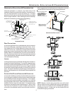
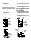
I
NSTALLATION
P
OSITIONS
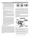
This furnace may be installed in an upright position or horizontal
on either the left or right side panel. Do not install this furnace on
its back. For upright upflow furnaces, return air ductwork may be
attached to the side panel(s) and/or basepan. For horizontal
upflow furnaces, return air ductwork must be attached to the
basepan. For both upright or horizontal counterflow furnaces,
return ductwork must be attached to the basepan (top end of the
blower compartment). NOTE: Ductwork must never be attached
to the back of the furnace. Contact your distributor for proper
airflow requirements and number of required ductwork connec-
tions. Refer to “Recommended Installation Positions” figure for
appropriate installation positions, ductwork connections, and re-
sulting airflow arrangements.
2. Inspect the venting system for proper size and horizontal
pitch, as required by the National Fuel Gas Code, ANSI
Z223.1 or the Natural Gas and Propane Installation Code,
CSA B149.1-05 and these instructions. Determine that there
is no blockage or restriction, leakage, corrosion and other
deficiencies which could cause an unsafe condition.
3. As far as practical, close all building doors and windows
and all doors between the space in which the appliance(s)
connected to the venting system are located and other
spaces of the building.
4. Close fireplace dampers.
5. Turn on clothes dryers and any appliance not connected to
the venting system. Turn on any exhaust fans, such as range
hoods and bathroom exhausts, so they shall operate at maxi-
mum speed. Do not operate a summer exhaust fan.
6. Follow the lighting instructions. Place the appliance being
inspected in operation. Adjust thermostat so appliance shall
operate continuously.
7. Test for spillage from draft hood appliances at the draft hood
relief opening after 5 minutes of main burner operation. Use
the flame of a match or candle.
8. If improper venting is observed during any of the above
tests, the venting system must be corrected in accordance
with the National Fuel Gas Code ANSI Z223.1/NFPA 54 and/
or National Gas and Propane Installation Code CSA
B149.1-05.
9. After it has been determined that each appliance connected
to the venting system properly vents when tested as out-
lined above, return doors, windows, exhaust fans, fireplace
dampers and any other gas burning appliance to their previ-
ous conditions of use.
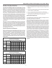
If resizing is required on any portion of the venting system, use
the appropriate table in Appendix G in the latest edition of the
National Fuel Gas Code ANSI Z223.1 and/or CSA B149.1-05
Installation Codes.
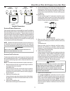
THERMOSTAT L OCATION
The thermostat should be placed approximately five feet from the
floor on a vibration-free, inside wall in an area having good air
circulation. Do not install the thermostat where it may be influ-
enced by any of the following:
• Drafts, or dead spots behind doors, in corners, or under
cabinets.
• Hot or cold air from registers.
• Radiant heat from the sun.
• Light fixtures or other appliances.
• Radiant heat from a fireplace.
• Concealed hot or cold water pipes, or chimneys.