


47
N
ORMAL
S
EQUENCE
OF
O
PERATION
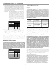
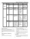
SYSTEM TROUBLESHOOTING
NOTE: Refer to the instructions accompanying the CT compatible
outdoor AC/HP unit for troubleshooting information.
Refer to the Troubleshooting Chart in the Appendix for a listing of
possible furnace error codes, possible causes and corrective
actions.
N
ORMAL
S
EQUENCE
OF
O
PERATION
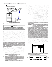
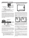
POWER U P
The normal power up sequence is as follows:
• 115 VAC power applied to furnace.
• Integrated control module performs internal checks.
• Integrated control module displays
88
88
8
88
88
8 on dual 7-segment
display LED’s.
• Integrated control module monitors safety circuits
continuously.
• Furnace awaits call from thermostat. Dual 7-segment LED’s
display
00
00
0
PP
PP
P while awaiting call from thermostat.
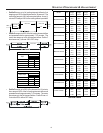
HEATING M ODE
The normal operational sequence in heating mode is as follows:
• R and W1 (or R and W1/W2) thermostat contacts close,
initiating a call for heat.
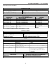
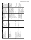
LED LED
Status
Indication Possible Causes Corrective Action(s) Notes & Cautions
Off
x Normal condition x None x None x None
1 Flash
x Communications
Failure
x Communications
Failure
x Depress Learn Button
x Verify that bus BIAS
and TERM
dipswitches are in the
ON position.
x Depress once
quickly for a power-
up reset
x Depress and hold
for 2 seconds for
an out-of-box reset
Red
Communications
LED
2 Flashes
x Out-of-box reset x Control power up
x Learn button
depressed
x None x None
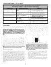
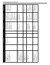
Off
x No power
x Communications
error
x No power to furnace
x Open fuse
x Communications error
x Check fuses and
circuit breakers;
replace/reset
x Replace blown fuse
x Check for shorts in
low voltage wiring in
furnace/system
x Reset network by
depressing learn
button
x Check data 1/ data 2
voltages
x Turn power OFF
prior to repair
1 Steady
Flash
x No network found x Broken/ disconnected
data wire(s)
x Furnace is installed as
a legacy/ traditional
system
x Check
communications
wiring (data 1/ data 2
wires)
x Check wire
connections at
terminal block
x Verify furnace
installation type
(legacy/ traditional or
communicating)
x Check data 1/ data 2
voltages
x Turn power OFF
prior to repair
x Verify wires at
terminal blocks are
securely twisted
together prior to
inserting into
terminal block
x Verify data1 and
data voltages as
described above
Rapid
Flashing
x Normal network
traffic
x Control is “talking” on
network as expected
x None x None
Green Receive
LED
On Solid
x Data 1/ Data 2
miss-wire
x Data 1 and data 2
wires reversed at
furnace, thermostat,
or CT™ compatible
outdoor AC/HP
x Short between data 1
and data 2 wires
x Short between data 1
or data 2 wires and R
(24VAC) or C (24VAC
common)
x Check
communications
wiring (data 1/ data 2
wires)
x Check wire
connections at
terminal block
x Check data 1/ data 2
voltages
x Turn power OFF
prior to repair
x Verify wires at
terminal blocks are
securely twisted
together prior to
inserting into
terminal block
x Verify data1 and
data voltages as
described above