


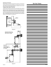

Page 8 R-5627
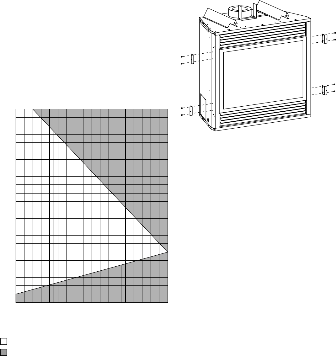
VENTING RUNS
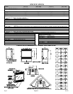
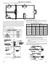
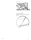
To Use the Vent Graph (Figure 8)
1. Determine the height of the center of the horizontal vent pipe. Using
this dimension on the Sidewall Vent Graph, locate the point it
intersects with the slanted graph line.
2. From the point of this intersection, draw a vertical line to the bottom
of the graph.
3. Select the indicated dimension, and position the unit in accordance
with same.
EXAMPLE A:
If the vertical dimension from the floor of the unit is 22.5 feet, the
horizontal run to the outer wall flange must not exceed 6.5 feet.
EXAMPLE B:
If the vertical dimension from the floor of the unit is 6.5 feet, the
horizontal run to the outer wall flange must not exceed 14.5 feet.
SPECIAL NOTE: For each 45 degree elbow installed in the horizontal
run, the length of the horizontal run MUST be reduced by 18" (45cm).
This does not apply if the 45 degree elbows are installed on the vertical
part of the vent system.
Example: According to the chart the maximum horizontal vent length
is 20' and if two 45 degree elbows are required in the horizontal vent it
must be reduced to 17'.
The maximum number of 45 degree elbows permitted per side wall
installation is two (2). These elbows can be installed in either the vertical
or horizontal run.
Venting Graph (Dimensions in Feet)
Figure 8
Acceptable vertical and horizontal vent run.
Unacceptable vertical and horizontal vent run.
B
20181716 1915141311109 12
A
24
23
21
20
22
18
17
16
14
15
19
25
11
13
12
9
10
6
7
4
3
5
8
76543
VERTICAL DIMENSION FROM THE BOTTOM OF THE UNIT
VERTICAL DIMENSION
FROM THE
BOTTOM
OF THE
UNIT
TO THE CENTER OF THE HORIZONTAL PIPE
TO THE
CENTER
OF THE
HORIZONTAL PIPE
SIDEWALL VENTING GRAPH
()(DIMENSIONS
IN FEET)
HORIZONTAL RUN
8
Installation
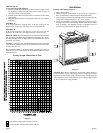
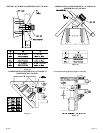
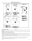
Framing and Finishing (Figure 9)
1. Choose unit location.
2. Frame in fireplace with a header across the top. It is important to
allow for finished face when setting the depth of the frame.
3. Attach fireplace to frame using adjustable frame. Preset depth to suit
facing material (adjustable to 1/2", 5/8" or 3/4" depths).
4. Use (8) 1/2" hex-head screws supplied in hardware package, to screw
through slotted holes in drywall strip and then screw into pre-drilled
holes on fireplace side. Measure from face of fireplace to face of
drywall strip to determine final depth. (See Figure 9)
Figure 9
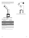
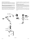
Attention: When DVF is installed in optional full cabinet mantel or
corner mantel the (4) four nailing flanges shown in Figure 6 will not be
installed on the side of outer casing. The DVF will be attached to the full
cabinet mantel or corner mantel with the (2) two nailing flanges located
on the top of the outer casing assembly.