


R-5627 Page 31
Maintenance and Service
PLEASE NOTE
It is normal for appliances fabricated of steel to give off some
expansion and/or contraction noised during the start up or cool
down cycle. Similar noises are found with your furnace heat
exchanger or car engine.
It is not unusual for your Empire gas fireplace to give off some odor the
first time it is burned. This is due to the curing of the paint and any
undetected oil from the manufacturing process.
Please ensure that your room is well ventilated - open all windows.
It is recommended that you burn your Empire unit for at least six (6)
hours the first time you use it. If optional fan kit has been installed,
place fan in the "OFF" position during this time.
IMPORTANT: Turn off gas before servicing appliance. It is
recommended that a competent service technician perform these check-
ups at the beginning of each heating season.
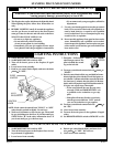
• Clean Burner and Control Compartment
Keep the control compartment, logs, and burner areas surrounding the
logs clean by vacuuming or brushing at least twice a year.
Cleaning Procedure
1. Turn off pilot light at gas valve.
2. Remove glass front. (See Glass Removal)
3. Vacuum burner compartment.
4. Reinstall glass front.
5. Ignite pilot. (See Lighting/Operating Section of Manual)
6. Operate the pilot burner and visually check to make sure the flame
pattern appears similar to the pictorial illustration shown in Figure
45. If it appears abnormal call a service person.
• Check Vent System
The appliance and venting system should be inspected before initial
use and at least annually by a qualified field service person. Inspect
the external vent cap on a regular basis to make sure that no debris
is interfering with the air flow.
Glass Cleaning
It will be necessary to clean the glass periodically. During start-up
condensation, which is normal, forms on the inside of the glass and
causes lint, dust and other airborne particles to cling to the glass surface.
Also initial paint curing may deposit a slight film on the glass. It is
therefore recommended that the glass be cleaned two or three times with
a non-abrasive household cleaner and warm water (we recommend gas
fireplace glass cleaner). After that the glass should be cleaned two or
three times during each heating season depending on the circumstances
present.
General Glass Information
WARNING: Do not operate appliance with the glass front
removed, cracked or broken. Replacement of the glass should be
done by a licensed or qualified service person.
Only glass approved for use by the manufacturer in fireplace may be used
for replacement. The glass replacement should be done by a licensed or
qualified service person.
WARNING:
1. The use of substitute glass will void all product warranties.
2. Care must be taken to avoid breakage of the glass.
3. Under no circumstances should this appliance be operated without
the glass front or with a broken glass front. Replacement of the glass
(with gasket) as supplied by the manufacturer should be done by a
qualified service person.
4. Do not abuse the glass by striking or hitting the glass.
WARNING: Do not use abrasive cleaners on glass. Do not
attempt to clean glass when glass is hot.
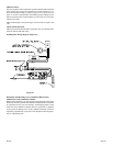
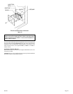
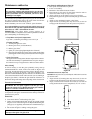
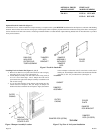
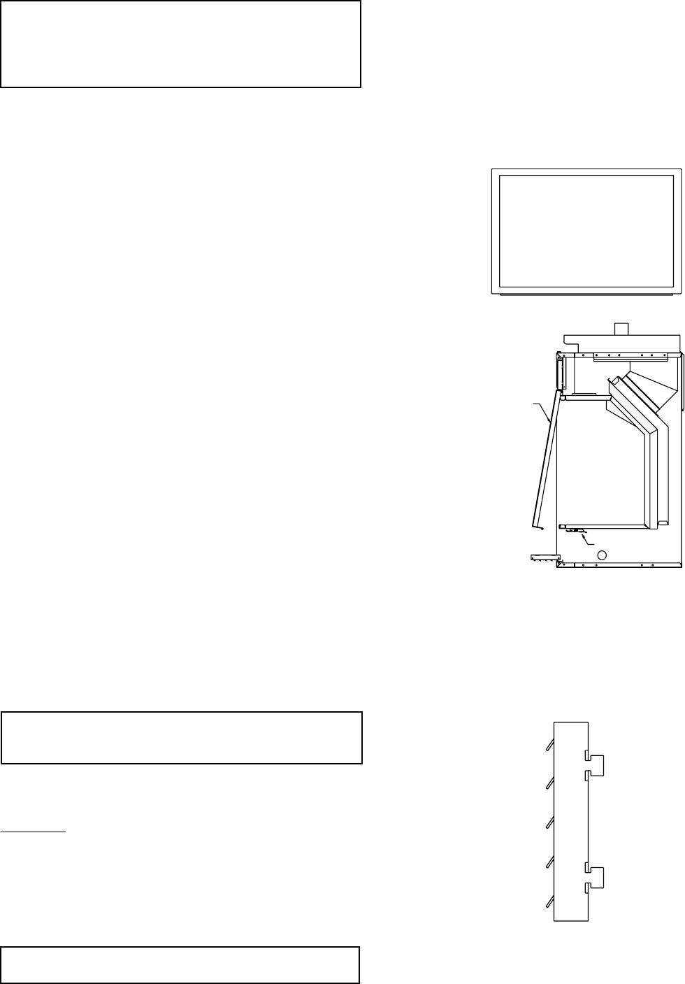
Glass Removal and Replacement (Figure 49)
1. Push up and outward to remove top louver.
2. Lower door assembly.
3. Release two door latches at bottom of firebox.
4. Grasp bottom of glass frame, lift glass frame upward in order to
release glass frame from lip on top of firebox.
5. Align and place top of glass frame over lip on top of firebox.
6. Grasp bottom of glass frame, push inward and place glass frame onto
firebox.
7. Attach two door latches onto bottom of glass frame.
8. Align and insert (4) mounting tabs on top louver with (4) slots on
casing top. Push downward to lock the top louver into position.
DOOR LATCH
DOOR LATCH
GLASS FRAME
GLASS FRAME
Figure 49
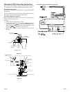
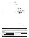
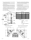
Installation of Louvers (Figure 50)
Attention: The top louver has (4) mounting tabs. The bottom louver has
(2) clearance holes.
1. Align and insert (4) mounting tabs on top louver with (4) slots on
casing top. Push downward to lock the top louver into position.
2. Align (2) clearance holes on bottom louver with (2) screw holes on
casing. Attach bottom louver to casing with (2) 10 x 1/2" screws.
Figure 50