


Page 22 R-5627
Initial Lighting
Upon completing the gas line or turning the gas valve on after it has been
in the "OFF" position, a small amount of air will be in the lines. When
first lighting the fireplace, it will take a few minutes for the lines to purge
themselves of this air. Once the purging is complete, the fireplace will
light and operate satisfactorily.
Subsequent lightings of the appliance will not require such purging if the
gas valve is not turned to "OFF."
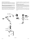
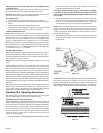
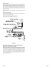
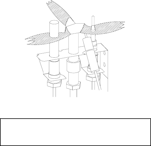
Pilot Flame (Figure 42)
The thermopile/thermocouple (standing pilot) tips should be covered
with flame.
Figure 42
Attention: Only, after the fireplace has been converted to a
heater can the 750 millivolt wall thermostat, GWSG-T or battery
operated remote control with thermostat, FRBTC-1 be used. See
installation of heater baffle on Page 5.
OPERATING INSTRUCTIONS
ON/OFF/REMOTE Switch
DVF is equipped with an ON/OFF/REMOTE switch. A wire harness is
attached to the ON/OFF/REMOTE switch. The red, black and green
(wires) female push-ons attach to the ON/OFF/REMOTE switch. At the
opposite end of the wire harness, the black and green (wires) female
push-ons attach to the gas valve. An additional green wire and the red
wire, which are stripped and bare, will attach to the 750 millivolt wall
thermostat accessory, or, to one of the other accessories that can be
purchased for use with your log set.
Operation of ON/OFF/REMOTE Switch with no Accessories
To ignite main burner, turn the control knob on the gas valve from the
PILOT position to the ON position. Turn the ON/OFF/REMOTE switch
from the OFF position to the ON position. The additional green wire and
red wire, which are stripped and bare are not used.
Operation of ON/OFF/REMOTE Switch with Accessories
750 Millivolt Wall Thermostat, GWSG-T
Connect the green and red, stripped and bare, wires on the ON/OFF/
REMOTE switch wire harness to the wall thermostat. Turn the ON/OFF/
REMOTE switch to the REMOTE position. Set the wall thermostat to
the desired temperature.
It is important to use wire of a gauge proper for the length of the wire:
RECOMMENDED WIRE GAUGES
Maximum Wire
Length Gauge
1' to 10' 18
10' to 25' 16
25' to 35' 14
Wall Switch, FWS-1
Connect the green and red, stripped and bare, wires on the ON/OFF/
REMOTE switch wire harness to the wall switch. Turn the ON/OFF/
REMOTE switch to the REMOTE position. Pivot the rocker switch on
the FWS-1 to the ON position.
Battery Operated Remote Control, FRBC-1 and FRBTC-1
Connect the green and red, stripped and bare, wires on the ON/OFF/
REMOTE switch wire harness to the remote receiver that is a component
in the FRBC-1 and FRBTC-1. Turn the ON/OFF/REMOTE switch to
the REMOTE position. Follow instructions in the FRBC-1 and FRBTC-
1 to complete installation.
Note: If batteries fail in FRBC-1 or FRBTC-1, and immediate heat is
desired, turn the ON/OFF/REMOTE switch from the REMOTE posi-
tion to the ON position.
Electric (120 volt) Operated Remote Control, FREC-1
Connect the green and red, stripped and bare, wires on the ON/OFF/
REMOTE switch wire harness to the wires on remote receiver that is a
component in the FREC-1. Turn the ON/OFF/REMOTE switch to the
REMOTE position. Follow instructions in the FREC-1 to complete
installation.
Note: If electric (120 volt) fails in FREC-1, and immediate heat is
desired, turn the ON/OFF/REMOTE switch from the REMOTE position
to the ON position.
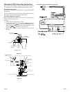
Wiring of ON/OFF/REMOTE Switch with 750 Millivolt Wall
Thermostat Accessory and Another Accessory
Connect the green and red, stripped and bare, wires on the ON/OFF/
REMOTE switch wire harness to the 750 millivolt wall thermostat AND
to the remote receiver that is a component in the FRBC-1, FREC-1 OR
to the FWS-1, wall switch.
1. Connect (1) wire from the 750 millivolt wall thermostat and (1) wire
from appropriate accessory to the GREEN, stripped and bare wire
from the ON/OFF/REMOTE wire harness.
2. Connect (1) wire from the 750 millivolt wall thermostat and (1) wire
from appropriate accessory to the RED, stripped and bare wire from
the ON/OFF/REMOTE wire harness.
Note: When the appliance is in the MANUAL mode and the batteries
fail in the FRBC-1 or if the electric (120 volt) fails in the FREC-1, and
immediate heat is desired, turn the ON/OFF/REMOTE switch from
the REMOTE position to the ON position.
Manual Operation
1. Turn ON/OFF/REMOTE switch to REMOTE position.
2. Turn wall thermostat OFF.
3. Turn accessory, FRBC-1, FRBTC-1, FREC-1 or FWS-1, ON.
Appliance is now in the manual mode. You must turn the appliance
ON or OFF with appropriate accessory.
Wall Thermostat Operation
1. Turn the ON/OFF/REMOTE switch to REMOTE position.
2. Turn accessory, FRBC-1, FRBTC-1, FREC-1 or FWS-1, OFF.
3. Turn wall thermostat ON and set appropriate temperature. Wall
thermostat will cycle the appliance ON and OFF.
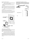
Installation of Remote Receiver
Place remote receiver on the floor of fireplace behind the louver as far
forward as possible.
Attention: The velcro loop and hook are not necessary in this installation
but can be used to secure remote receiver.