


Page 34 R-5627
Wiring
The appliance, when installed, must be electrically grounded in
accordance with local codes or, in the absence of local codes, with the
National Electrical Code, ANSI/NFPA 70, if an external electrical source
is utilized. This appliance is equipped with a three-prong [grounding]
plug for your protection against shock hazard and should be plugged
directly into a properly grounded three-prong receptacle. Do not cut
or remove the grounding prong from this plug. For an ungrounded
receptacle, an adapter, which has two prongs and a wire for grounding,
can be purchased, plugged into the ungrounded receptacle and its wire
connected to the receptacle mounting screw. With this wire completing
the ground, the appliance cord plug can be plugged into the adapter and
be electrically grounded.
CAUTION: Label all wires prior to disconnection when servicing
controls. Wiring errors can cause improper and dangerous operation.
Verify proper operation after servicing.
Blower Motor
The blower motor does not have oiling holes. Do not attempt to oil the
blower motor.
Blower Wheels
The blower wheels will collect lint and could require periodic cleaning.
If the air output decreases or the noise level increases, it indicates a dirty
blower wheel. Remove fan and clean blower wheels.
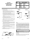
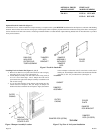
Installing Optional Fan Kit
1. If applicable, turn OFF electric supply to fireplace.
2. Lower the bottom louver.
3. With a 5/16" socket, loosen but do not remove either left screw or
right screw that attaches bottom louver to fireplace side.
4. When the screw is sufficiently loosened you will be able to pull
and pivot the bottom louver out of fireplace.
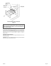
5. Centered in the rear are (2) weld studs which protrude upward into
the bottom of fireplace for attachment of fan.
6. Insert fan into interior, bottom of fireplace. The clearance holes on
fan mounting bracket must be facing toward the front of fireplace.
Do not damage gas inlet supply line when fan is inserted into
fireplace.
7. Align and place (2) clearance holes that are 2 1/2" from end of fan
mounting bracket onto (2) weld studs.
8. Use (2) wing nuts to attach fan to weld studs.
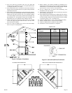
9. Located in the right, front are (2) weld studs which protrude
upward into the bottom of fireplace for attachment of speed
control.
10. Insert speed control into interior, bottom of fireplace. Align and
place (2) clearance holes on speed control onto (2) weld studs.
11. Use (2) wing nuts to attach speed control to weld studs.
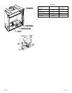
12. Remove top louver from firebox.
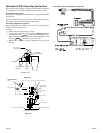
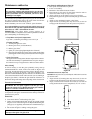
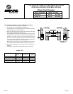
13. Refer to Figure 1 for mounting hole location on right side of
firebox top that applies to your appliance. Measure from front
edge of firebox top to determine mounting hole location. Remove
appropriate screw from firebox top.
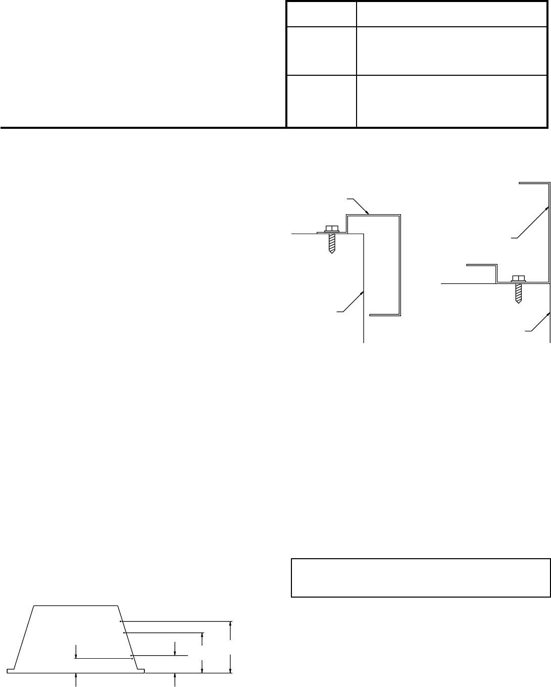
14. Refer to Figure 2 for fan control bracket location that applies to
your firebox. Align clearance hole on fan control bracket with
screw hole on firebox top. Attach fan control bracket to firebox
top with one (1) screw from Step 13.
15. Route fan control wires between the inner casing and outer casing.
16. Connect fan control wires to speed control wires.
17. Plug speed control electric cord into junction box on the right side
of fireplace.
18. Replace and attach top louver and bottom louver onto fireplace.
19. Installation of fan kit is completed.
Figure 1
Figure 2
VFFB-30
VFC30
VFC30
DVF/DVT
DVF/DVT
FIREBO X TOP
FIREBO X TOP
VFFB-36/VFC 3 6
VFFB-36/VFC 3 6
VFFB-42 /VFC 42
VFFB-42 /VFC 42
12 1/2
"12 1/2"
9 1/4"
9 1/4"
3 1/2"
3 1/2"
3 3/4"
3 3/4"
DVF/DVT UNITS
DVF/DVT UNITS
FAN CONTROL
FA N CONTROL
BRAC KET
VFFB/VFC UNITS
VFFB/VFC UN I TS
FAN CONTROL
FA N CONTROL
BRAC KET
FIREBO X
FIREBO X
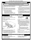
OPTIONAL
AUTOMATIC FAN KIT
INSTALLATION
INSTRUCTIONS
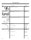
OPTIONAL
FAN MODEL NUMBER
FB-BK-2 VFFB-30C VFFB-36C VFFB-42C
VFFB-36D VFFB-42D
DVF-36 DVF-36IP
DVF-42 DVF-42IP
FKA-160 VFC-30 VFC-36 VFC-42
VFD-36 VFD-42
DVT/R-36 DVT/RE-36
DVT/R-42 DVT/RE-42