


R-5627 Page 19
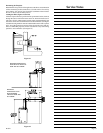
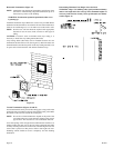
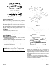
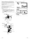
Installing the Vent System in a Chase
A chase is a vertical box like structure built to enclose the gas appliance
and/or it's vent system. Vertical vent runs on the outside of a building
may be, but are not required to be installed inside a chase.
Figure 35
CAUTION: Treatment of firestop spacers and construction of the
chase may vary with the type of building. These instructions are not
substitutes for the requirements of local building codes. Therefore,
your local building codes must be checked to determine the
requirements for these steps.
NOTE: When installing this vent system in a chase, it is always good
building practice to insulate the chase as you would the outside walls of
your home. This is especially important for cold climate installations.
Upon completion of building your chase framing, install the vent system
by following the instructions in this manual. Remember to build the
chase large enough so that minimum clearance of combustible materials
(including insulation) to the vent system are maintained.
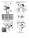
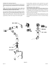
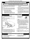
Reassembly and Resealing Vent Pipe System
Attach adapter pipe to vent cover in either the vertical or horizontal
position, replace horizontal and vertical pipe lengths, elbows and
horizontal or vertical termination kit.
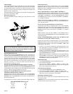
All vent system components lock into place by sliding the concentric
pipe section with four (4) equally spaced interior beads onto the
appliance collar or previously installed component end with four (4)
equally spaced indented sections. When the internal beads of each
starting 6-5/8 inch outer pipe line up, rotate pipe section clockwise 90°
(approximately 3 inches). The vent pipe is now locked together.
Continue replacing components per the vent system configuration. Be
certain that each succeeding vent component is securely fitted and
locked into the preceding component in the vent system.
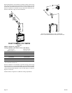
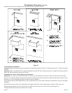
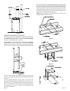
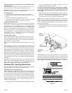
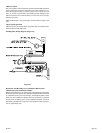
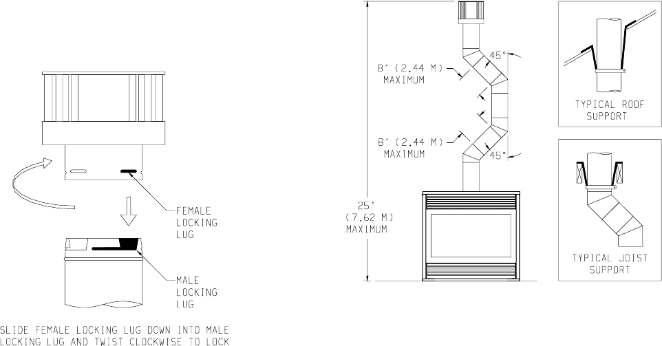
Vertical Through the Roof Applications (Figure 36)
Your Gas Fireplace has been approved for:
a) Vertical installations up to 25 feet in height.
b) Two sets of 45 degree elbow offsets within these vertical installations.
From 0 to a maximum of 8 ft. a vent pipe can be used between
elbows.
c) Wall straps must be used to support offset pipe every 4'.
This applications will require that you first determine the roof pitch and
use the appropriate venting components.
Figure 36
Leak Testing Gas Line
Consult the current National Fuel Gas Code, ANSI Z223.1 CAN/CGA-
B149 (.1 or .2) installation code.
Compounds used on threaded joints of gas piping shall be resistant to the
action of liquefied petroleum gases. The gas lines must be checked for
leaks by the installer. This should be done with a soap solution watching
for bubbles on all exposed connections, and if unexposed, a pressure test
should be made.
Never use an exposed flame to check for leaks. Appliance must be
disconnected from piping at inlet of control valve and pipe capped or
plugged for pressure test. Never pressure test with appliance
connected; control valve will sustain damage!
NOTE: The gas control is equipped with a captured screw type pressure
test point, therefore it is not necessary to provide a 1/8" test point up
stream of the control.
A gas valve and ground joint union should be installed in the gas line
upstream of the gas control to aid in servicing. It is required by the
National Fuel Gas Code that a drip line be installed near the gas inlet. This
should consist of a vertical length of pipe tee connected into the gas line
that is capped on the bottom in which condensation and foreign particles
may collect.
When using copper or flex connector use only approved fittings. Always
provide a union so that gas line can be easily disconnected for burner or
fan servicing. See gas specification for pressure details and ratings.
The appliance and it's individual shut off valve must be disconnected from
supply piping system during any pressure testing of that system at test
pressures in excess of 1/2 psig (3.5kPa).
The appliance must be isolated from the gas supply piping system by
closing its individual manual shut off valve during any pressure testing
of the gas supply piping system at test pressures equal to or less than 1/
2 psig (3.5kPa).
Attention! If one of the procedures results in pressures in excess of 1/2
psig (14" w.c.) (3.5 kPa) on the fireplace gas valve, it will result in a
hazardous condition
.