


Page 12 R-5627
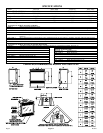
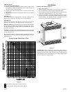
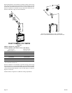
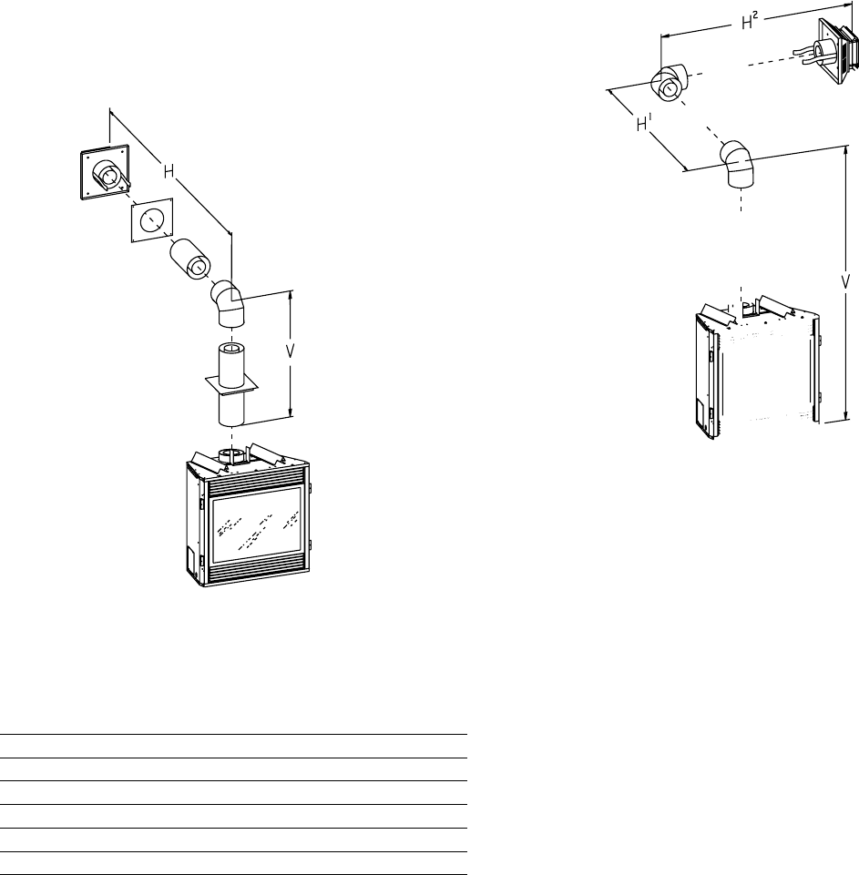
Figure 20 and Chart 1 lists examples of possible venting systems using
one (1) 90° elbow. Eight (8) feet is listed as maximum vertical vent run
with 20 feet of maximum horizontal vent run. Vertical dimensions are
based on centerline to centerline of pipe. Horizontal dimensions are
based on centerline of pipe to end of termination.
SEE CHART FOR PERMISSIBLE "H" AND "V" DIMENSIONS
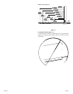
SEE CHART FOR PERMISSIBLE "H" AND "V" DIMENSIONS
Figure 20
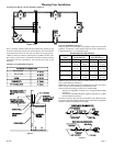
CHART 1 (Figures 21, 22 and 23)
Venting with One (1) 90
° Elbow or Two (2) 90° Elbows
Total Vertical Total Horizontal
(With Fire Box) V H
1
or H
1
+ H
2
4.5' minimum 3' maximum
4.5' minimum 4' maximum
5' minimum 8' maximum
6' minimum 12' maximum
7' minimum 15' maximum
8' minimum 20' maximum
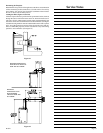
25' maximum vertical
20' maximum horizontal run
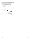
Figure 21 and Chart 1 list examples of possible venting systems using
two (2) 90° elbows. V is listed as minimum vertical dimensions and H1
+ H2 is listed as total of maximum horizontal dimensions. The maximum
vertical and horizontal distances for two (2) 90° elbows as shown in
Figure 21 are 20 feet.
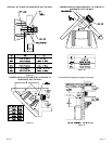
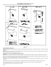
Attention: Refer to Figure 8 for additional venting requirements.
SEE CHART FOR PERMISSIBLE "H" AND "V" DIMENSIONS
NOTE: H1 AND H2 MUST BE ADDED TOGETHER TO USE CHART