


Page 16 R-5627
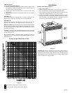
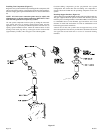
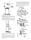
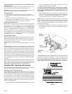
Installing Vent Components (Figure 27)
Begin the vent system installation by installing the first component, 90°
elbow to the starting collars or straight pipe on the top of the appliance,
then the straight pipe length and then horizontal or vertical termination
kit.
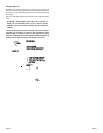
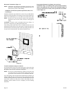
NOTE: All 8 inch outer connection joints must be sealed with
aluminum tape or silicone sealant rated above 300
°F/149°C. The 5
inch inner flue joints do not require any sealant.
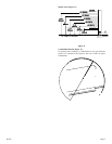
All vent system components lock into place by sliding the concentric
pipe section with four (4) equally spaced interior beads onto the
appliance collar or previously installed component end with four (4)
equally spaced indented sections. When the internal beads of each
starting 8 inch outer pipe line up, rotate pipe section clockwise 90°
(approximately 3 inches). The vent pipe is now locked together.
Continue adding components per the pre-planned vent system
configuration. Be certain that each succeeding vent component is
securely fitted and locked into the preceding component in the vent
system.
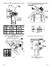
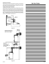
Installing Support Brackets (Figure 28)
A horizontal pipe support MUST BE used for each 3 feet of horizontal run.
The pipe supports should be placed around 8 inch diameter pipe and
nailed in place to framing members. There MUST BE a 3 inch clearance
to combustibles above 8 inch diameter pipe and elbows and 1 inch
clearance on both sides and bottom of 8 inch to combustibles on all
horizontal pipe sections and elbows.
Vertical runs of this vent systems must be supported every 4 feet
above the appliance flue outlet by wall brackets attached to the 8 inch
vent pipe and secured with nails or screws to structural framing
members.
Figure 27