


R-5627 Page 37
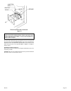
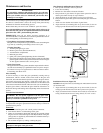
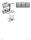
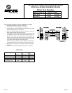
Figure 5 Caulk and Install Duct Termination
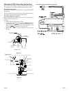
WALL
DUCT TERMINATION
RAIN CAP
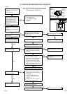
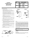
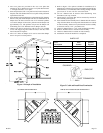
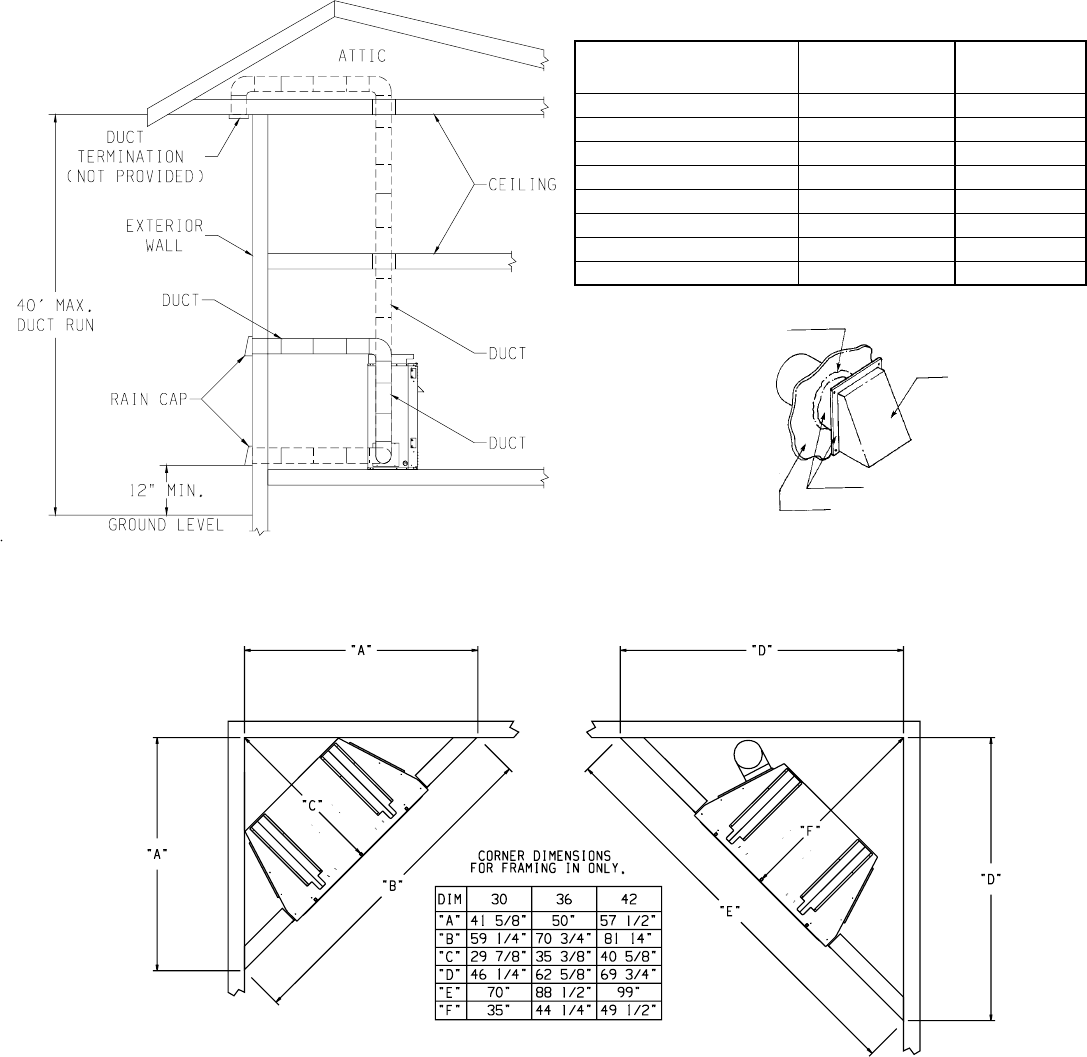
Figure 4 Example of Installation
4. Two cover plates are provided in kit. Use cover plate that
measures 6 3/8" in height. Do not use cover plate that measures
7" in height. Discard 7" cover plate.
5. Insert and position 6 3/8" cover plate into left, interior bottom of
fireplace. The 3/8" diameter hole in cover plate will be positioned
upward and to the left.
6. Insert damper rod through damper rod bracket and 3/8" diameter
hole in cover plate. Insert damper rod into 1/4" diameter hole in
damper door tab. Place smooth side of 1/2" diameter pushnut
over end of damper rod. Press the pushnut onto the damper rod
approximately 1/8". The pushnut will prevent the damper rod
from falling out of 1/4" diameter hole in damper door tab.
7. Attach cover plate to support legs with (4) 10 x 1/2" provided
screws. The support legs are on the left side, to the rear, in the
interior bottom of fireplace.
8. The 1 1/4" offset on damper rod is used to secure the damper
door in an open or closed position.
9. Refer to Figure 4 for options available for installation of 6"
diameter duct. The duct run can be a maximum length of 40 feet.
Insulated duct is recommended when ducting through a heated
space. Note: 6" C vent or 6" flex vent can be used.
10. Cut a 6" diameter hole in structure after determining duct
termination (rain cap) location.
11. Caulk exterior of structure that will be contacted by outside air
tube assembly (See Figure 5).
12. Insert outside air tube assembly into 6" diameter hole in structure.
Align clearance holes on rain cap with clearance holes on outside
air tube assembly. Attach rain cap and outside air tube assembly
to structure with (6) 1 1/2" provided screws.
13. Attach 6" diameter duct to 1 1/2" collar on damper assembly.
14. Route 6" diameter duct to outside air tube assembly.
15. Attach 6" diameter duct to outside air tube assembly.
16. Installation of fresh air intake kit is completed.
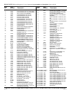
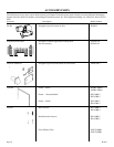
PARTS LIST
Part Part Quantity
Description Number Supplied
Damper Assembly 10098 1
6 3/8" Cover Plate 10083 1
Damper Rod Bracket 10086 1
Rain Cap 10124 1
Damper Rod R-4182 1
Pushnut R-4607 1
10 x 1/2" Screw R-2737 6
10 x 1 1/2" Screw R-1134 6
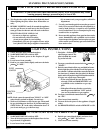
NO ELBOWS USED ON FRESH AIR KIT
WHEN 90° OR 45° ELBOWS ARE USED ON FRESH AIR KIT
CAULKING