


R-5627 Page 17
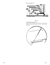
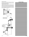
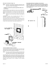
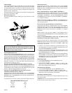
STUD WALL
STUD WALL
FLUE OUTLET
FLUE OUTLET
(25.4mm)
PIPE STRAP
PIPE STRAP
48"
(1219mm)
1" MIN.
1" MIN.
Figure 28
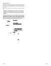
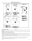
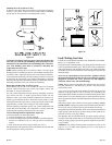
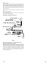
Installing Firestops (Figures 29, 30, 31 and 32)
Firestops are required for safety whenever the vent system passes
through an interior wall, an exterior wall, or a ceiling. These firestops act
as a firebreak heat shield and as a means to insure that minimum
clearances are maintained to the vent system.
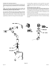
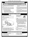
Cut a 10-3/8 inch x 12-3/8 inch hole in wall. Position firestop (SD-1249)
on interior side of wall for 10-3/8 inch x 12-3/8 inch hole. Attention:
Wall firestop hole is off-set towards bottom of wall opening. Secure with
nails or screws. Continue the vent run through the firestop. (See Figure 29)
WALL FIRESTOP
HOLE IS OFF-SET TOWARDS
HOLE IS OFF-SET TOWARDS
BOTTOM OF WALL OPENING.
BOTTOM OF WALL OPENING.
12 3/8
12 3/8
10 3/8
10 3/8
Figure 29
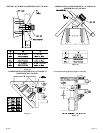
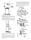
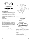
Vertical runs of this system which pass through ceilings require the use
of ONE (1) ceiling firestop at the hole in each ceiling through which the
vent passes.
Position a plumb bob directly over the center of the vertical vent
component and mark the ceiling to establish the center point of the vent.
Drill a hole or drive a nail through this center point and check the floor
above for any obstructions such as wiring or plumbing runs. Reposition
the fireplace and vent system, if necessary, to accommodate ceiling
joists and/or obstructions.
Cut a 10-1/2 inch x 10-1/2 inch hole through the ceiling, using the center
point previously marked. Frame the hole with framing lumber the same
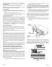
size as the ceiling joists. (See Figure 30) If the area above the ceiling is
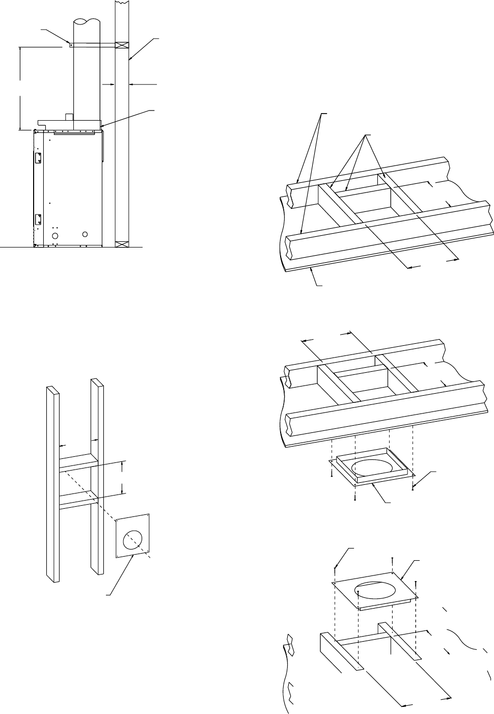
NOT an attic, position and secure the ceiling firestop (SD-1263) on the
ceiling side of the previously cut and framed hole. (See Figure 31) If the
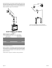
area above the ceiling is an attic, position and secure the firestop on top
of the previously framed hole. (See Figure 32)
NOTE: Remove insulation from the framed area in the attic before
installing the firestop and/or vent pipe.
10
1/2"
10
1/2"
267mm
10 1/2"
10 1/2"
267m
m
267mm
CEILING BELOW
CEILING BELOW
NEW FRAMING
NEW FRAMING
EXISTING CEILING JOISTS
EXISTING CEILING JOISTS
Figure 30
10 1/2"
10
1/2"
267mm
CEILING FIRESTOP
CEILING FIRESTOP
NAILS, 4 REQUIRED
NAILS, 4 REQUIRED
10 1/2"
10
1/2"
267mm
Figure 31
CEILING FIRESTOP
CEILING FIRESTOP
10 1/2"
10
1/2"
267mm
10 1/2"
10
1/2"
267mm
NAILS, 4 REQUIRED
NAILS, 4 REQUIRED92 98.774 11F725.751 168.1054650.476 163m4608189 l424.622.61569315 182.0822.615689 m319.38 335.294 l546.475 33.7.948 m346.4 10659.10l41645 4 173.189 5 139.1079 885464 l43583 l4l5.245 c36.380 179.245 c36.3352 71.245 c3457 m467.838 358331 60.262 35.7122 75.245 c36.380 179.245 c36.3352 71.245 c3457 m467.838 358331 60.262 35.7122 75.0.2679 495 58 62.948679 42.292 35.29.3834.1772 62.94859 42.65 167.29.383432 34 62.94859 4.7769 132.Q4