


R-5627 Page 7
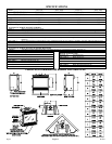
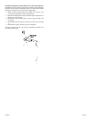
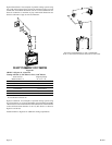
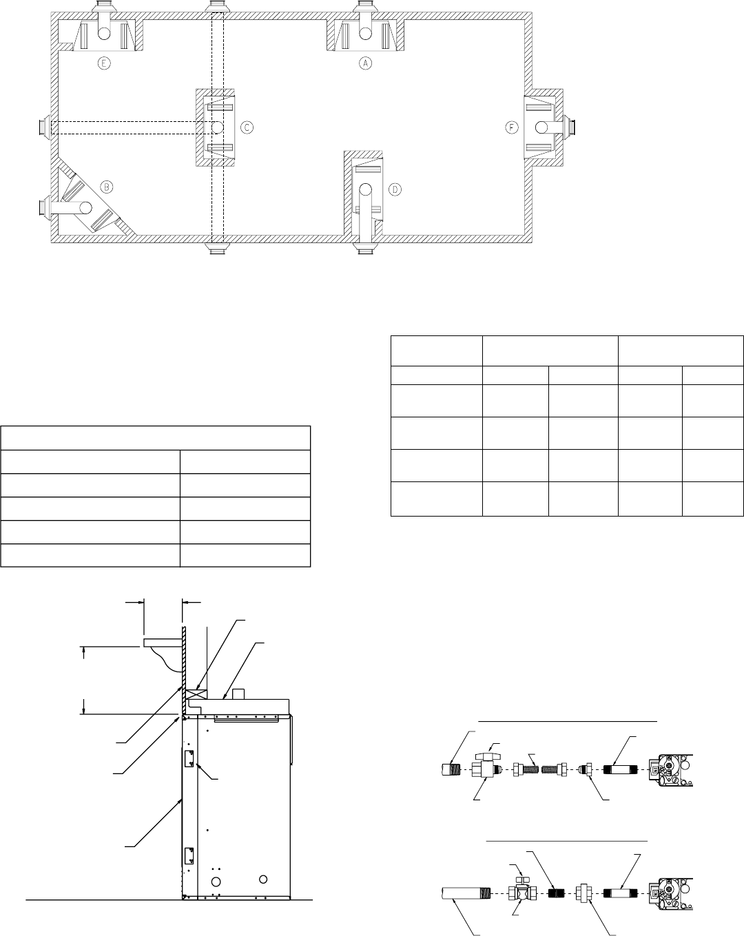
Gas Line Installation (Figure 7)
The gas pipeline can be brought in through the right or left side of the
appliance. Consult the current National Fuel Gas Code, ANSI Z223.1
CAN/CGA-B149 (.1 or .2) installation code.
Recommended Gas Pipe Diameter
Pipe Length Schedule 40 Pipe Tubing, Type L
(Feet) Inside Diameter Outside Diameter
Nat. L.P. Nat. L.P.
0-10 1/2" 3/8" 1/2" 3/8"
1.3 cm 1.0 cm 1.3 cm 1.0 cm
10-40 1/2" 1/2" 5/8" 1/2"
1.3 cm 1.3 cm 1.6 cm 1.3 cm
40-100 1/2" 1/2" 3/4" 1/2"
1.3 cm 1.3 cm 1.9 cm 1.3 cm
100-150 3/4" 1/2" 7/8" 3/4"
1.9 cm 1.3 cm 2.2 cm 1.9 cm
Note: Never use plastic pipe. Check to confirm whether your local codes
allow copper tubing or galvanized.
Note: Since some municipalities have additional local codes, it is always
best to consult your local authority and installation code.
The use of the following gas connectors is recommended:
— ANS Z21.24 Appliance Connectors of Corrugated Metal Tubing
and Fittings
— ANS Z21.45 Assembled Flexible Appliance Connectors of Other
Than All-Metal Construction
The above connectors may be used if acceptable by the authority having
jurisdiction. The State of Massachusetts requires that a flexible appliance
connector cannot exceed three feet in length.
1/2 FLEX TUBING
1/2 FLEX TUBING
1/2 NPT
1/2 NPT
NIPPLE
1/2 NPT NIPPLE
1/2 NPT NIPPLE
1/2 NPT UNION
1/2 NPT UNION
1/2 NPT X 1/2
1/2 NPT X 1/2
FLARE FITTING
FLARE FITTING
TEE HANDLE
TEE HANDLE
1/2 NPT CLOSE NIPPLE
1/2 NPT CLOSE NIPPLE
TEE HANDLE
TEE HANDLE
1/2 NPT GAS SUPPLY
1/2 NPT GAS SUPPLY
1/2 NPT X 1/2 FLARE
1/2 NPT X 1/2 FLARE
SHUT OFF VALVE
SHUT OFF VALVE
1/2 NPT SHUT
1/2 NPT SHUT
OFF VALVE
OFF VALVE
RIGID GAS LINE CONNECTION
RIGID GAS LINE CONNECTION
FLEXIBLE GAS LINE CONNECTION
FLEXIBLE GAS LINE CONNECTION
1/2 NPT GAS SUPPLY
1/2 NPT GAS SUPPLY
Figure 7
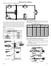
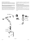
Note:** Island (C) and Room Divider (D) installation is possible as long
as the horizontal portion of the vent system (H) does not exceed 20 feet
with a minimum vertical run of 8 feet. See details in Venting Section.
*When you install your Direct Vent Fireplace in (D) Room divider or (E)
Flat on wall corner positions, a minimum of 6 inches clearance must be
maintained from the perpendicular wall and the front edge of the
appliance.
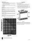
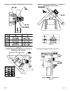
Clearance to Combustibles (Figure 6)
2" x 4" HEADER
2" x 4" HEADER
STAND OFF
STAND OFF
3" (76mm) HEIGHT
3" (76mm) HEIGHT
ABOVE TOP OF
FIREPLACE
GLASS FRONT
GLASS FRONT
TOP FRAMING
LEDGE
FINISHED WALL
FINISHED WALL
ADJUSTABLE
NAILING
FLANGES
SEE MANTLE CHART
SEE MANTLE CHART
FOR MAXIMUM MANTLE
FOR MAXIMUM MANTLE
DEPTH
SEE MANTLE CHART
SEE MANTLE CHART
FOR MINIMUM HEIGHT
FOR MINIMUM HEIGHT
OF MANTLE ABOVE UNIT
OF MANTLE ABOVE UNIT
CLEARANCE TO COMBUSTIBLES
CLEARANCE TO COMBUSTIBLES
BACK 0" (0 mm)
BACK 0" (0 mm)
SIDE 0" (0 mm)
SIDE 0" (0 mm)
FLOOR 0” (O mm)
FLOOR 0” (O mm)
TOP STAND OFF 0" (0 mm)
TOP STAND OFF 0" (0 mm)
TOP FRAMING LEDGE 0" (0 mm)
TOP FRAMING LEDGE 0" (0 mm)
Figure 6
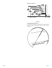
Locating Your Direct Vent Gas Fireplace (Figure 5)
Figure 5
Planning Your Installation
BACK SPACER
SIDE SPACER