


Page 26 R-5627
Intermittent Pilot Operating Instructions
The intermittent pilot (120/24 volt system) is ON when the main burner
is ON. When the main burner is OFF the intermittent pilot is OFF.
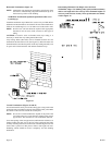
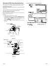
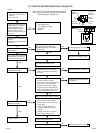
IP-Model Pilot (Figure 44)
This fireplace is using a Honeywell "Smart Valve" system for intermittent
pilot ignition.
On a call for flame the control turns on a 24 volt mini hot surface ignitor
which lights a pilot that in turn lights the main burner.
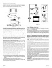
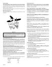
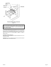
Pilot Flame Adjustment (Figure 45)
The pilot flame should envelop 3/8 to 1/2 inch (10 to 13mm) of the tip
of the flame rod. (See Figure 44)
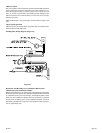
To adjust:
1. Remove the pilot adjustment cover screw.
2. Turn the inner adjustment screw clockwise to decrease
or counterclockwise to increase pilot flame. Pilot adjust-
ment is shipped at full flow rate. Turn the inner adjustment screw
clockwise
if the inlet pressure is too high.
3. Replace the cover screw after the adjustment to prevent gas
leakage.
BURNER
PILOT
HOT SURFACE
IGNITOR
FLAME
ROD
GROUND
ELECTRODE
3/8" TO 1/2"
PILOT FLAME
IP-MODEL PILOT
Figure 44
ON
OFF
IGNITOR
CONTROL
INLET PRESSURE TAP
OUTLET PRESSURE TAP
PILOT ADJUSTMENT-
UNDER CAP SCREW
PILOT OUTLET
PRESSURE REGULATOR
ADJUSTMENT-UNDER CAP
SCREW
GAS FLOW
IGNITOR
CONTROL
TO 24 V. THERMOSTAT
TO 24 V. COMMON ON TRANSFORMER
TO 24 V."HOT" ON TRANSFORMER
WIRING
I P-MODEL GAS VALVE AND WIRING
IGNITOR-PILOT ASSY.
Figure 45
Intermittent Pilot Wiring Diagram (Figure 46)