


R-5627 Page 21
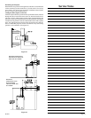
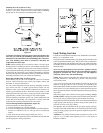
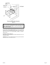
Placing Lava (Decorative) Rock in Front of Grate and Burner Pan
on Fireplace Floor
Spread lava rocks on fireplace floor in front of grate. The rocks are for
decorative effect and are not required for fireplace operation.
Attention: Do not place lava rocks on logs, branches or rock wool. The
lava rocks should only be placed on the fireplace floor.
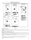
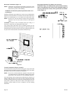
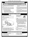
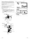
Glass Replacement
1. Align and place top of glass frame over lip on top of firebox.
2. Grasp bottom of glass frame, push inward and place glass frame onto
firebox.
3. Attach two door latches onto bottom of glass frame.
4. Align and insert (4) mounting tabs on top louver with (4) slots casing
top. Push downward to lock the top louver into position.
Checking Manifold Pressures
Both Propane and Natural gas valves have a built-in pressure regulator
in the gas valve. Natural gas models will have a manifold pressure of
approximately 3.5" w.c. (.871kPa) at the valve outlet with the inlet
pressure to the valve from a minimum of 4.5" w.c. (1.120kPa) for the
purpose of input adjustment to a maximum of 10.5" w.c. (2.615kPa).
Propane gas models will have a manifold pressure approximately 10.0"
w.c. (2.49kPa) at the valve outlet with the inlet pressure to the valve from
a minimum of 11.0" w.c. (2.739kPa) for the purpose of input adjustment
to a maximum of 13.0" w.c. (3.237kPa).
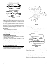
FLAME APPEARANCE
Flames from the pilot (rear right back side of the pan burner) as well as
the main flame should be visually checked as the log set is installed.
In normal operation at full rate after 10 to 15 minutes, the flame appear-
ance should be sets of yellow flames.
NOTE: Flames will be random by design, flame height will go up and
down.
Glowing embers (rock wool) can cover the pan burner in between the
front and middle logs, but very little is necessary to cover this area. Ex-
cess rock wool material causes the yellow flame to become orange and
stringy. Apply just enough to obtain slow glow and a bright yellow flame.
During manufacturing, fabricating and shipping, various components of
this appliance are treated with certain oils, films or bonding agents. These
chemicals are not harmful, but may produce annoying smoke and smells
as they are burned off during the initial operation of the appliance, possibly
causing headaches or eye or lung irritation. This is a normal and temporary
occurrence.
The initial break-in operation should last 2-3 hours with the burner at the
highest setting. Provide maximum ventilation by opening windows or
doors to allow odors to dissipate. Any odors remaining after this initial
break-in will be slight and will disappear with continued use.
Standing Pilot Operating Instructions
The standing pilot (750 millivolt system) is a continuous burning pilot.
The pilot remains ON even when the main burner is OFF.
750 Millivolt System (Figures 40 and 41)
When you ignite the pilot, the thermocouple produces millivolts (electrical
current) which energizes the magnet in the gas valve. After 30 seconds
to 1 minute time period you can release the gas control knob and the pilot
will stay ON. Allow your pilot flame to operate an additional one (1) to
two (2) minutes before you turn the gas control knob from the PILOT
position to the ON position. This time period allows the millivolts
(electrical current) to build-up to a sufficient level allowing the gas
control to operate properly.
1. Follow the SAFETY and LIGHTING INSTRUCTIONS for standing
pilot controls found in this manual and on labels found in control
compartment behind the door assembly.
CAUTION: During the initial purging and subsequent lightings,
never allow the gas valve control knob to remain depressed in the
"pilot" position without pushing the red ignitor button at least once
every second.
2. During the heating season, leave the control valve knob in the "ON"
position. This will allow the pilot flame to remain lit. Turn the burner
flame on or off with the fireplace ON/OFF rocker switch, wall
switch, remote control kit or 750 millivolt wall thermostat.
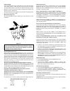
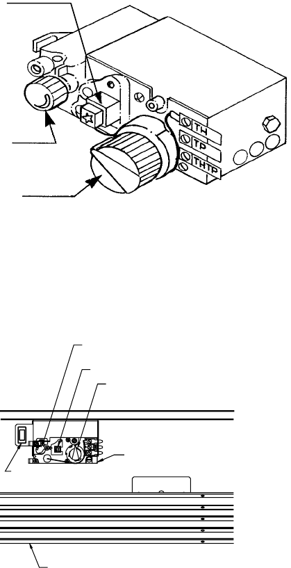
NOTE: The gas control valve allows you to increase or decrease the
height of the main burner flame. The control valve has a pressure
regulator with a knob as shown in Figure 40. Rotate the knob clockwise
to "HI" to increase the flame height and counterclockwise to "LO" to
decrease the flame height.
3. When the heating season is over, turn the on/off switch to "OFF" and
the control valve to "OFF". The system, including the pilot light, will
be shut down.
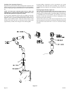
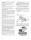
Figure 40
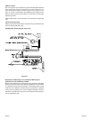
The OWNER should carefully read and follow these operating instructions
at all times. Lower the door assembly to view the gas controls for the
fireplace. Your model has a push button piezo ignitor, the fireplace has a
STANDING PILOT IGNITION SYSTEM. (See Figure 41) Follow the
Safety, Lighting and Operating instructions applicable to your fireplace.
PIEZO IGNITOR
PIEZO IGNITOR
VALVE CONTROL KNOB
VALVE CONTROL KNOB
VARIABLE REGULATOR
VARIABLE REGULATOR
("HI"-"LO") KNOB
("HI"-"LO") KNOB
REMOTE/ON/OFF SWITCH
REMOTE/ON/OFF SWITCH
DOOR ASSEMBLY (SHOWN OPEN)
DOOR ASSEMBLY (SHOWN OPEN)
GAS VALVE
GAS VALVE
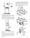
Figure 41
HI/LO
REGULATOR
CONTROL
KNOB
PIEZO
IGNITOR