


INDOOR AIRFLOW AND AIRFLOW ADJUSTMENTS
For cooling operation, the recommended airflow is
350 to 450 cfm per each 12,000 Btuh of rated cooling
capacity.
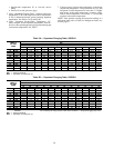
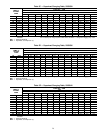
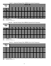
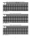
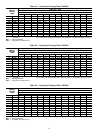
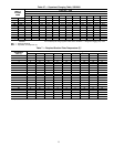
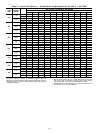
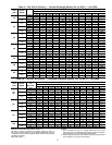
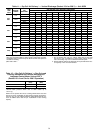
Tables 8-11 show airflows at several external static pres-
sures. Table 12 shows airflow for Fan Only and Cooling modes
for ICM units. Tables 13-15 show accompanying pressure
drops for wet coils, electric heaters, and filters. Refer to these
tables to determine the airflow for the system being
installed.
NOTE: Be sure that all supply- and return-air grilles are open,
free from obstructions, and adjusted properly.
Disconnect electrical power to the unit before changing
blower speed. Electrical shock can cause personal in-
jury or death.
Airflow can be changed by changing the lead connections
of the blower motor.
Unit 50SS two- or 3-speed motors are factory wired for
low speed operation. Units 50SX024, 036 and 048 (460 v)
two- or 3-speed motors are factory wired for low speed. Units
50SX030 and 042 are factory wired for medium speed.
For 208/230-v and A.O. Smith 460-v Blower Motors:
The motor leads are color-coded as follows:
3-SPEED 2-SPEED
black = high speed black = high speed
blue = medium speed red = low speed
red = low speed
To change the speed of the blower motor, remove the fan
motor speed leg lead from the indoor (evaporator) fan relay
(IFR) and replace with lead for desired blower motor speed.
Insulate the removed lead to avoid contact with chassis parts.
For 460-v GE Motors:
The motor leads are color coded as follows:
3-SPEED 2-SPEED
black = high black = high
blue = jumper blue = jumper
orange = medium red = low
red = low
To change the speed of the blower motor, remove red fan
motor speed lead from the indoor (evaporator) fan relay (IFR).
The motor speed lead is attached to terminal BM. Insulate
removed lead end to avoid contact with chassis parts. On
3-speed motors only, connect orange lead to IFR. To select
high speed, separate the black (female QC) from the blue
lead (male QC) and connect the black lead to IFR. Insulate
the blue lead to avoid contact with any chassis parts.
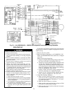
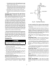
For Integrated Control Motors (ICM) — To configure the 50SX
unit, move the 5 Easy Select board wires to the terminals
which control the airflow. Refer to the Easy Select interface
board (Fig. 32) located next to the terminal and to Fig. 33
and 34.
Perform the following steps for basic system
configuration.
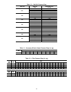
AUX HEAT RANGE (VIO)
NOTE: If no heater is installed, this step can be omitted.
The airflow for electric heat is selected with theAUX HEAT
RANGE terminals. Refer to Table 3 and the installation in-
structions for electric heaters for minimum airflow required
for safe heater operation. Refer to table below for the avail-
able airflows. Each select pin is configured for a certain air-
flow. The airflow will be supplied in the Heating mode on
air conditioners when electricheat is the primary heating source.
The preset factory default selection is the highest airflow.
TERMINAL 1234
Available
Airflow (Cfm)
1365 1470 1680 1840
AC/HP SIZE (BLU) — The preset factory default selection
for AC/HP SIZE (air conditioner/heat pump) is set to
400 cfm/ton. The selection pins are configured for 350 cfm/
ton and 400 cfm/ton.
TYPE (ORN) — The TYPE is a preset factory default se-
lection. The preset factory default setting is AC for the 50SX
units. Default setting should not be altered.
AC/HP CFM ADJUST (BLK) — The preset factory default
selection is MED. Selections HI and LO will adjust the air-
flow supplied for all operational modes (see table below).
The selection options allow installer to adjust airflow to meet
such individual needs as noise and static compensation, etc.
MODE
FAN
ONLY
COOLING HEATING
LO - Adjust −15% −10% −10%
HI - Adjust 15% 10% 10%
AC/HP TIME DELAY (GRY) — Four motor operation delay
options are provided to customize system operation. See list-
ing below:
OPTION DESCRIPTION
30-Sec On/60-Sec
Off Delay
Profile (Terminal 1)
Used when it is desirable to allow system
coils time to heat up or cool down prior to
airflow.
No Delay Option
(Terminal 2)
Used for servicing or when other compo-
nents are used to perform the delay
function.
30-Sec Off Delay
(Terminal 3)
Preset factory default setting for 50SX
units.
45-Sec Off Delay
(Terminal 4)
Enhances system efficiency.
UNIT CONTROLS — All compressors have the following
internal-protection controls.
High-Pressure Relief Valve — This valve opens when the
pressure differential between the low and high side becomes
excessive.
Compressor Overload — This overload interrupts power to
the compressor when either the current or internal tempera-
ture become excessive, and automatically resets when the
internal temperature drops to a safe level.
This overload may require up to 60 minutes (or longer) to
reset; therefore, if the internal overload is suspected of being
open, disconnect the electrical power to the unit and check
the circuit through the overload with an ohmmeter or con-
tinuity tester.
34