


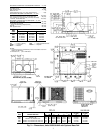
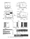
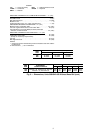
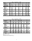

REQUIREDCLEARANCESTOCOMBUSTIBLEMATERIAL —in.(mm)
Unit Top ................................14(356)
Duct Side of Unit ............................2(51)
Side Opposite Ducts ........................14(356)
Bottom of Unit .................................0
Vertical Discharge First 12 in. (305) of Supply Duct .......1(25)
NECESSARY REQUIRED CLEARANCES — in. (mm)
Between Units, Control Box Side ................42(1067)
Unit and Ungrounded Surfaces, Control Box Side ......36(914)
Unit and Block or Concrete Walls and Other Grounded
Surfaces, Control Box Side ...................42(1067)
REQUIRED CLEARANCES FOR SERVICING — in. (mm)
Evaporator Coil Access Side ...................30(762)
Control Box Access Side ......................30(762)
(Except for Necessary Requirements)
Unit Top ................................36(914)
Side Opposite Ducts ........................30(762)
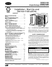
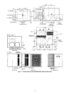
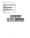
UNIT
50SS
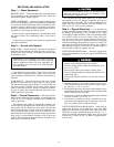
CENTER OF GRAVITY (in./mm)
XYZ
018 19.6/499 21.7/551 10.6/269
024 22.5/570 20.9/530 10.0/254
030 22.1/561 20.3/516 10.0/253
036 21.2/538 19.9/506 9.9/251
042 21.3/540 19.9/506 11.3/286
LEGEND
CG — Center of Gravity NEC — National Electrical Code
COND — Condenser REQ’D — Required
MAT’L — Material
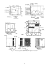
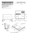
NOTES:
1. Clearances must be maintained to prevent recirculation of air from
outdoor-fan discharge.
2. Dimensions in ( ) are in millimeters.
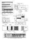
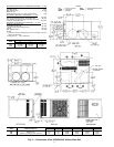
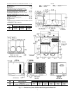
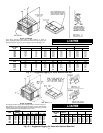
UNIT
50SS
ELECTRICAL
CHARACTERISTICS
UNIT WT CORNER WT (Lb/Kg)
UNIT HEIGHT
(in./mm)
DIMENSION
(in./mm)
Lb Kg A B C D E F
018 208/230-1-60 208 95 61/28 43/20 69/31 35/16 24.1/613 18.2/462
024 208/230-1-60 237 108 60/27 54/25 92/42 31/14 24.1/613 18.2/462
030 208/230-1-60, 208/230-3-60 254 115 61/28 58/26 96/44 39/18 24.1/613 18.2/462
036 208/230-1-60, 208/230-3-60, 460-3-60 270 123 75/35 48/22 109/50 37/17 24.1/613 18.2/462
042 208/230-1-60, 208/230-3-60, 460-3-60 300 135 81/40 57/26 117/53 45/20 28.1/714 22.2/563
Fig. 2 — Dimensions; Units 50SS018-042 Without Base Rail
2