


Step 7 — Install Electrical Connections
The unit cabinet must have an uninterrupted, unbroken
electrical ground to minimize the possibility of personal
injury if an electrical fault should occur. This ground
may consist of an electrical wire connected to the unit
wire-binding screw in the control compartment, or con-
duit approved for electrical ground when installed in ac-
cordance with NEC (National Electrical Code), ANSI/
NFPA (latest edition) (in Canada, Canadian Electrical
Code CSA C22.1) and local electrical codes. Failure to
adhere to this warning could result in personal injury or
death.
Failure to follow these precautions could result in dam-
age to the unit being installed:
1. Make all electrical connections in accordance with
NEC ANSI/NFPA (latest edition) and local elec-
trical codes governing such wiring. In Canada, all
electrical connections must be in accordance with CSA
Standard C22.1 Canadian Electrical Code Part 1
and applicable local codes. Refer to unit wiring
diagram.
2. Use only copper conductor for connections between
field-supplied electrical disconnect switch and unit.
DO NOT USE ALUMINUM WIRE.
3. Be sure that high-voltage power to unit is within op-
erating voltage range indicated on unit rating plate.
On 3-phase units, ensurethat phases are balanced within
2%. Consult local power company for correction of
improper voltage and/or phase imbalance.
4. Insulate low-voltage wires for highest voltage con-
tained within conduit when low-voltage control wires
are run in same conduit as high-voltage wires.
5. Do not damage internal components when drilling
through any panel to mount electrical hardware, con-
duit, etc.
HIGH-VOLTAGE CONNECTIONS — The unit must have
a separate electrical service with a field-supplied, water-
proof disconnect switch mounted at, or within sight from the
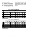
unit. Refer to the unit rating plate for maximum fuse/circuit
breaker size and minimum circuit amps (ampacity) for wire
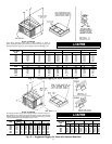
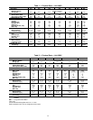
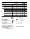
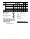
sizing. See Tables 4A and 4B for electrical data.
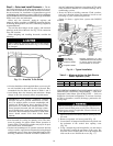
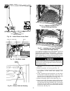
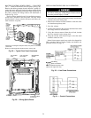
The field-supplied disconnect may be mounted on the unit
over the high-voltage inlet hole. See Fig. 2-9.
If the unit has an electric heater, a second disconnect may
be required. Consult the Installation, Start-Up and Service
Instructions provided with the accessory for electrical serv-
ice connections.
Operation of unit on improper line voltage constitutes
abuse and may cause unit damage that could affect
warranty.
ROUTING POWER LEADS INTO UNIT — Use only cop-
per wire between disconnect and unit. The high-voltage leads
should be in a conduit until they enter the duct panel; con-
duit termination at the duct panel must be watertight. Run
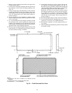
the high-voltage leads through the knockout on the duct panel
(see Fig. 28 for location and size). When the leads are inside
the unit, run leads up the high-voltage raceway to the line
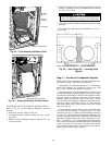
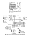
wiring splice box (Fig. 29). For single-phase units, connect
leads to the black and yellow wires; for 3-phase units,
connect the leads to the black, yellow, and blue wires (see
Fig. 30).
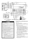
CONNECTING GROUND LEAD TO WIRE-BINDING
SCREW — Refer to Fig. 29 and 30. Connect the ground
lead to the chassis using the wire-binding screw in the wir-
ing splice box.
ROUTING CONTROL POWER WIRES — STD NON-
ICM UNITS (24 v) — For all units except 50SS060, form
a drip-loop with the thermostat leads before routing them
into the unit. Route the thermostat leads through grommeted
hole provided in unit (see Fig. 28) into unit control power
splice box. Connect thermostat leads to unit control power
leads as shown in Fig. 31.
For 50SS060 units, remove knockout in the duct panel (see
Fig. 28).
Remove the rubber grommet from the installer’s packet
(included with unit) and install it in the knockout opening.
Route thermostat wires through grommet providing a drip
loop at the panel. Connect low-voltage leads to the thermo-
stat as shown in Fig. 31.
The unit transformer supplies 24-v power for complete
system including accessory electrical heater. Transformer is
factory wired for 230-v operation. If supply voltage is 208 v,
rewire transformer primary as described in the Special Pro-
cedures for 208-v Operation section on page 24.
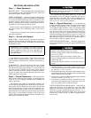
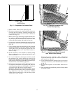
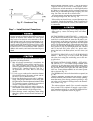
Fig. 27 — Condensate Trap
21