


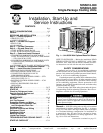
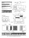
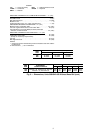
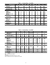

REQUIREDCLEARANCESTOCOMBUSTIBLEMATERIAL —in.(mm)
Unit Top ................................14(356)
Duct Side of Unit ............................2(51)
Side Opposite Ducts ........................14(356)
Bottom of Unit .................................0
Vertical Discharge First 12 in. (305) of Supply Duct .......1(25)
NECESSARY REQUIRED CLEARANCES — in. (mm)
Between Units, Control Box Side ................42(1067)
Unit and Ungrounded Surfaces, Control Box Side ......36(914)
Unit and Block or Concrete Walls and Other Grounded
Surfaces, Control Box Side ...................42(1067)
REQUIRED CLEARANCES FOR SERVICING — in. (mm)
Evaporator Coil Access Side ...................30(762)
Control Box Access Side ......................30(762)
(Except for Necessary Requirements)
Unit Top ................................36(914)
Side Opposite Ducts ........................30(762)
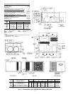
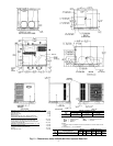
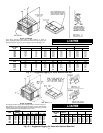
UNIT
50SS
CENTER OF GRAVITY (in./mm)
XYZ
018 19.5/495 21.7/551 12.9/328
024 22.1/562 20.9/532 12.3/313
030 21.8/554 20.4/519 12.3/312
036 21.0/533 20.1/509 12.2/310
042 21.0/532 20.1/510 13.6/344
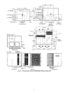
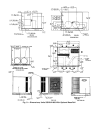
LEGEND
CG — Center of Gravity NEC — National Electrical Code
COND — Condenser REQ’D — Required
MAT’L — Material
NOTES:
1. Clearances must be maintained to prevent recirculation of air from
outdoor-fan discharge.
2. Dimensions in ( ) are in millimeters.
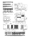
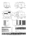
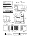
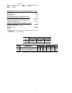
UNIT
50SS
ELECTRICAL
CHARACTERISTICS
UNIT WT CORNER WT (Lb/Kg)
UNIT HEIGHT
(in./mm)
DIMENSION
(in./mm)
Lb Kg A B C D E F
018 208/230-1-60 228 104 66/30 48/22 74/34 40/18 27.4/697 21.5/546
024 208/230-1-60 257 117 65/30 59/27 97/44 36/16 27.4/697 21.5/546
030 208/230-1-60, 208/230-3-60 274 125 66/30 63/29 101/46 44/20 27.4/697 21.5/546
036 208/230-1-60, 208/230-3-60, 460-3-60 290 132 81/37 53/24 114/52 42/19 27.4/697 21.5/546
042 208/230-1-60, 208/230-3-60, 460-3-60 320 146 86/39 62/28 122/55 50/23 31.4/798 25.5/648
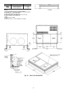
Fig. 3 — Dimensions; Units 50SS018-042 with Optional Base Rail
3