


RECEIVING AND INSTALLATION
Step 1 — Check Equipment
IDENTIFY UNIT —The unit model number and serial num-
ber are stamped on the unit identification plate. Check this
information against shipping papers.
INSPECT SHIPMENT — Inspect for shipping damage while
unit is still on shipping pallet. If unit appears to be damaged
or is torn loose from its anchorage, have it examined by trans-
portation inspectors before removal. Forward claim papers
directly to transportation company. Manufacturer is not re-
sponsible for any damage incurred in transit.
Check all items against shipping list. Immediately notify
the nearest Carrier Air Conditioning office if any item is
missing.
To prevent loss or damage, leave all parts in original pack-
ages until installation.
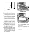
Step 2 — Provide Unit Support
ROOF CURB — Install accessory roof curb in accordance
with instructions shipped with curb. See Fig. 10. Install in-
sulation, cant strips, roofing, and flashing. Ductwork must
be attached to curb.
IMPORTANT: The gasketing of the unit to the roof
curb is critical for a watertight seal. Install gasketing
material supplied with the roof curb. Improperly ap-
plied gasketing also can result in air leaks and poor
unit performance.
Curb should be level to within
1
⁄
4
inch. This is necessary
for unit drain to function properly. Refer to accessory roof
curb installation instructions for additional information as
required.
SLAB MOUNT — Place the unit on a solid, level concrete
pad that is a minimum of 4 in. thick with 2 in. above grade.
The slab should extend approximately 2 in. beyond the cas-
ing on all 4 sides of the unit. Install a 6-in. gravel apron in
front of condenser-air inlet to prevent obstruction of airflow
by grass or shrubs. Do not secure the unit to the slab except
when required by local codes.
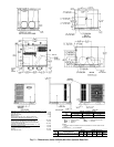
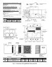
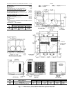
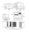
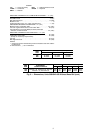
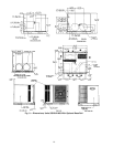
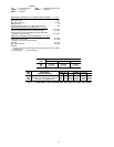
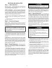
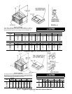
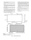
Step 3 — Provide Clearances — The required mini-
mum service clearances and clearances to combustibles are
shown in Fig. 2-9. Adequate ventilation and condenser air
must be provided.
The condenser fan pushes air through the condenser coil
and discharges it through louvers on the top cover, the deco-
rative grille, and the compressor access panel. Be sure that
the fan discharge does not recirculate to the condenser coil.
Do not locate the unit in either a corner or under an over-
head obstruction. The minimum clearance under a partial over-
hang (such as a normal house overhang) is 48 in. above the
unit top. The maximum horizontal extension of a partial over-
hang must not exceed 48 inches.
Do not restrict condenser airflow. An air restriction at
either the outdoor-air inlet or the fan discharge can be
detrimental to compressor life.
Do not place the unit where water, ice, or snow from
an overhang or roof will damage or flood the unit. Do not
install the unit on carpeting, tile, or other combustible ma-
terials. The unit may be installed on wood flooring or on
Class A, B, or C roof covering materials.
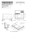
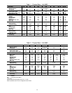
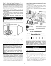
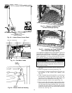
Step 4 — Rig and Place Unit — Use spreader bars
or crate top when rigging the unit. The units must be rigged
for lifting as shown in Fig. 11 and 12. Refer to Fig. 11 and
12 for rigging weights andTables 1 and 2 for operating weights.
Use extreme caution to prevent damage when moving the
unit. Unit must remain in an upright position during all rig-
ging and moving operations.The unit must be level for proper
condensate drainage; the ground-level pad or accessory roof
curb must be level before setting the unit in place. When a
field-fabricated support is used, be sure that the support is
level and that it properly supports the unit.
UNITS WITHOUTBASE RAILS —Accessory rigging brack-
ets are recommended to be used for rigging. Install brackets
as follows:
Secure screws and paint protectors solidly against unit
basepan to hold lifting brackets in position.
Never use lifting brackets when the temperature is be-
low −10 F (−23 C).
Never exceed 200 lbs per bracket of lifting force.
Never use lifting brackets for lifting other models of air
conditioning units.
Lifting point should be directly over the unit center of
gravity.
1. Position brackets as close to the corners of unit as pos-
sible. Be sure brackets are well outside of center of grav-
ity. (See Fig. 2, 4, 6, 8, and 11.)
2. Position paint protectors and foam strips between screws
and painted surface of unit. Tighten screws until they make
contact with the paint protectors.
3. Secure deviceor hook of sufficient strength tohole in bracket
as shown in detail ‘‘A’’ of Fig. 11.
4. If wood top is available, use it for a spreader bar to pre-
vent straps from damaging unit. If wood top is not avail-
able, use spreader bars of sufficient length.
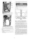
UNITS WITH OPTIONAL BASE RAILS — Keep unit up-
right and do not drop. Use spreader bars or top crate when
rigging unit. Rollers may be used to move unit across roof.
Level unit for proper condensate disposal. See Fig. 3, 5, 7,
and 9 for additional information. Lifting holes are provided
in base rails as shown in Fig. 12. Refer to rigging instruc-
tions on unit.
13