


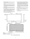

ACCESSORY DUCT FLANGE KIT INSTALLATION —
Refer to Fig. 26 for duct adapter dimensions and hole
locations.
1. Mark hole locations shown in Fig. 26.
2. At marked locations, drill holes using a no. 26 (.147-in.)
twist drill.
3. Partially secure duct flanges using two of the no. 10,
1
⁄
2
-in.
screws provided.
4. See the following caution. Using remaining holes in duct
flanges as templates, drill the remaining holes with the
no. 26 (.147-in.) drill.
Do not drill deeper than
1
⁄
2
-in. into shaded area shown
in Fig. 26. Damage to refrigerant coil could result.
5. Fully secure the duct flanges using the remaining screws
provided.
The finished kit installation accommodates a 14
3
⁄
4
-in. x
14
3
⁄
4
-in. duct.
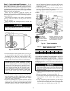
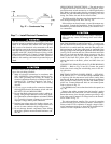
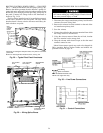
Step 6 — Provide for Condensate Disposal
NOTE: Be sure that condensate-water disposal methods com-
ply with local codes, restrictions, and practices.
Unit disposes of condensate through a
3
⁄
4
-in. NPT fitting
which exits through the compressor access panel. See
Fig. 2-9 for location of condensate connection.
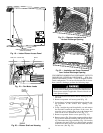
Condensate water can be drained directly onto the roof in
rooftop installations (where permitted) or onto a gravel apron
in ground-level installations. Install a field-supplied conden-
sate trap at end of condensate connection to ensure proper
drainage. Make sure that the outlet of the trap is at least
1 in. lower than the drain-pan condensate connection to pre-
vent the pan from overflowing. See Fig. 27. Prime the trap
with water. When using a gravel apron, make sure it slopes
away from the unit.
If the installation requires draining the condensate water
away from the unit, install a 2-in. trap using a
3
⁄
4
-in. FPT
connection. See Fig. 27. Make sure that the outlet of the trap
is at least 1 in. lower than the unit drain-pan condensate con-
nection to prevent the pan from overflowing. Prime the trap
with water. Connect a drain tube using a minimum of
3
⁄
4
-in.
PVC,
3
⁄
4
-in. CPVC, or
3
⁄
4
-in. copper pipe (all field supplied).
Do not undersize the tube. Pitch the drain tube downward at
a slope of at least 1 in. for every 10 ft of horizontal run. Be
sure to check the drain tube for leaks. Prime trap at the be-
ginning of the cooling season start-up.
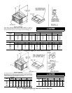
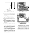
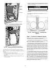
PLUG ASSEMBLIES
RACEWAY
FILLER
BRACKET
BLOWER
SHELF
Fig. 24 — Filler Bracket and Blower Shelf
HORIZONTAL DUCT OPENING
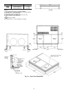
Fig. 25 — Housing Placed for Vertical Airflow
NOTE: Do not drill more than
1
⁄
2
-in. deep in shaded area.
Fig. 26 — Duct Flange Kit — Locating Holes
(Typical)
20