


Step 5 — Select and Install Ductwork — The de-
sign and installation of the duct system must be in accor-
dance with the standards of the NFPA (National Fire Protec-
tion Association) for installation of nonresidence-type air
conditioning and ventilating systems, NFPA90Aor residence-
type,NFPA90B;and/orlocalcodesandresidence-type,NFPA90B;
and/or local codes and ordinances.
Select and size ductwork, supply-air registers and
return-air grilles according to ASHRAE (American Society
of Heating, Refrigeration, and Air Conditioning Engineers)
recommendations.
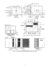
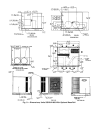
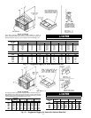
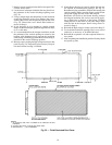
The unit has duct flanges on the supply- and return-air
openings on the side of the unit. See Fig. 2-9 for connection
sizes and locations.
When designing and installing ductwork, consider the
following:
When connecting ductwork to units, do not drill deeper
than
1
⁄
2
inch in shaded area shown in Fig. 13 or coil may
be damaged.
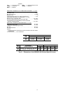
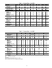
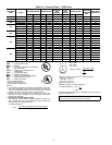
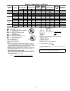
• All units should have field-supplied filters or accessory fil-
ter rack installed in the return-air side of the unit. Rec-
ommended sizes for filters are shown in Tables 1 and 2.
• Avoid abrupt duct size increases and reductions. Abrupt
change in duct size adversely affects air performance.
IMPORTANT: Use flexible connectors between
ductwork and unit to prevent transmission of vibra-
tion. Use suitable gaskets to ensure weathertight and
airtight seal. When electric heat is installed, use fire-
proof canvas (or similar heat resistant material) con-
nector between ductwork and unit discharge connec-
tion. If flexible duct is used, insert a sheet metal sleeve
inside duct. Heat resistant duct connector (or sheet metal
sleeve) should extend 24-in. from electric heater
element.
• Size ductwork for cooling air quantity (cfm). The mini-
mum air quantity for proper electric heater operation is
listed in Table 3. Heater limit switches may trip at air quan-
tities below those recommended.
• Insulate and weatherproof all external ductwork. Insulate
and cover with a vapor barrier all ductwork passing through
conditioned spaces. Follow latest Sheet Metal andAir Con-
ditioning Contractors National Association (SMACNA)
andAir Conditioning ContractorsAssociation (ACCA) mini-
mum installation standards for residential heating and air
conditioning systems.
• Secure all ducts to building structure. Flash, weather-
proof, and vibration-isolate duct openings in wall or roof
according to good construction practices.
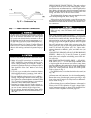
Figure 14 shows a typical duct system with 50SS,SX
installed.
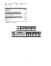
Table 3 — Minimum Airflow for Safe Electric
Heater Operation (Cfm)
SIZE
018* 024 030 036 042 048 060
700 700 875 1200 1225 1400 1750
*Unit 50SS only.
CONVERTING HORIZONTAL DISCHARGE UNITS TO
DOWNFLOW (VERTICAL) DISCHARGE — STD (Non-
Integrated Control Motor [Non-ICM] UNITS — Units are
shipped in a horizontal configuration. To convert a horizon-
tal unit for downflow (vertical) discharge, perform the fol-
lowing steps:
Before performing service or maintenance operations on
system, turn off main power to unit. Turn off accessory
heater power switch if applicable. Electrical shock can
cause personal injury.
1. Open all electrical disconnects before starting any serv-
ice work.
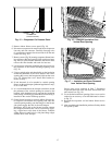
2. Remove evaporator coil access panel (Fig. 15).
3. Locate lances in basepan insulation that are placed over
the perimeter of the vertical duct opening cover
(Fig. 16).
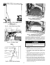
4. Using a straight edge and sharp knife, cut and remove
the insulation around the perimeter of the cover. Re-
move the screws securing the cover to the basepan and
slide out the cover. Discard the cover (Fig. 17).
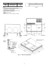
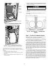
Fig. 13 — Area Not To Be Drilled
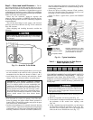
Power Wiring
Control Wiring
Condenser Airflow
Evaporator Airflow
*Separate disconnect per NEC
(NationalElectrical Code)required
for electric heater when single-
point connection is not used.
Fig. 14 — Typical Installation
16