


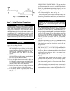
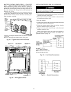

4. If the unit is equipped with a crankcase heater, start the
heater 24 hours before starting the unit. To start the heater
only, turn the thermostat to the OFF position and ener-
gize the electrical disconnect to the unit.
START-UP
Use the Start-Up Checklist supplied at the end of this book,
and proceed as follows:
Check for Refrigerant Leaks — Locate and repair
refrigerant leaks and charge the unit as follows:
1. Using both high- and low-pressure ports, locate leaks and
reclaim remaining refrigerant to relieve system
pressure.
2. Repair leak following accepted practices.
NOTE: Install a filter drier whenever the system has been
opened for repair.
3. Check system for leaks using an approved method.
4. Evacuate refrigerant system and reclaim refrigerant if no
additional leaks are found.
5. Charge unit with R-22 refrigerant, using a volumetric-
charging cylinder or accurate scale. Refer to unit rating
plate for required charge. Be sure to add extra refrigerant
to compensate for internal volume of filter drier.
Start-Up Cooling Section and Make
Adjustments
Complete the required procedures given in the Pre-
Start-Up section page 25 before starting the unit.
Do not jumper any safety devices when operating the
unit.
Do not operate the compressor when the outdoor tem-
perature is below 40 F (unless accessory low-ambient
kit is installed).
Do not rapid-cycle the compressor. Allow 5 minutes be-
tween ‘‘on’’ cycles to prevent compressor damage.
CHECKING COOLING CONTROL OPERATION — Start
and check the unit for proper cooling control operation as
follows:
1. Place room thermostat SYSTEM switch in OFF position.
Observe that blower motor startswhen FAN switch is placed
in ON position and shuts down when FAN switch is placed
in AUTO. position.
2. Place SYSTEM switch in COOL position and FAN switch
in AUTO. position. Set cooling control below room tem-
perature. Observe thatcompressor,condenser fan, and evapo-
rator blower motors start. Observe that cooling cycle shuts
down when control setting is satisfied.
3. When using an automatic changeover room thermostat,
place both SYSTEM and FAN switches in AUTO. posi-
tions. Observe that unit operates in Cooling mode when
temperature control is set to ‘‘call for cooling’’ (below
room temperature).
IMPORTANT: Three-phase, scroll compressors in
the 50SS048,060 and 50SX036-060 units are
direction-oriented. These units must be checked to
ensure proper compressor 3-phase power lead ori-
entation. If not corrected within 5 minutes, the in-
ternal protector will shut off the compressor. The
3-phase power leads to the unit must be reversed to
correct rotation. Whenturning backwards, scroll com-
pressors emit elevated noise levels, and the differ-
ence between compressor suction and discharge
pressures may be dramatically lower than normal.
CHECKINGANDADJUSTING REFRIGERANT CHARGE
— The refrigerant system is fully charged with R-22 refrig-
erant, and is tested and factory sealed.
NOTE: Adjustment of the refrigerant charge is not required
unless the unit is suspected of not having the proper R-22
charge.
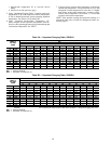
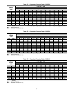
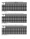
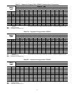
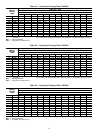
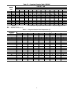
A superheat charging label is attached to the outside of
the compressor access door. The label includes a ‘‘Superheat
Charging Table’’ and a ‘‘Required Suction-Tube Tempera-
ture (F)’’ chart.
An accurate superheat, thermocouple-, or thermistor-type
thermometer, a sling psychrometer, and a gage manifold are
required when using the superheat charging method for evalu-
ating the unit charge. Do not use mercury or small dial-type
thermometers, because they are not adequate for this type of
measurement.
When evaluating the refrigerant charge, an indicated ad-
justment to the specified factory charge must always be
very minimal. If a substantial adjustment is indicated,
an abnormal condition exists somewhere in the cooling
system, such as insufficient airflow across either coil or
both coils.
Proceed as follows:
1. Remove caps from low- and high-pressure service
fittings.
2. Using hoses with valve core depressors, attach low- and
high-pressure gage hoses to low- and high-pressure serv-
ice fittings, respectively.
3. Start unit in cooling mode and let unit run until system
pressures stabilize.
4. Measure and record the following:
a. Outdoor ambient-air temperature (F db).
b. Evaporator inlet-air temperature (F wb).
27