


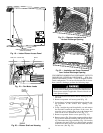
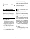

5. Remove indoor blower access panel (Fig. 18).
6. Disconnect evaporator-fan motor leads from evaporator-
fan relay and unit contactor. Carefully disengage wire
tie containing evaporator-fan motor leads from the unit
control box (Fig. 19).
7. Remove screws (Fig.20) securing evaporator blower hous-
ing to blower shelf and carefully slide out blower hous-
ing. There is a filler bracket attached to the blower shelf;
remove this filler bracket and retain for later use.
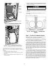
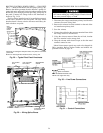
8. Locate lances in basepan insulation that are placed over
the perimeter of the vertical discharge opening cover
(Fig. 21).
9. Using a straight edge and sharp knife, cut the insulation
around the perimeter of the cover. Remove the screws
securing the cover to the basepan and slide out the cover
(Fig. 22). Discard the cover. Install filler bracket re-
moved in Step 7.
10. If unit ductwork is to be attached to vertical opening
flanges on the unit basepan (jackstand applications only),
do so at this time.
11. It is recommended that the basepan insulation around
the perimeter of the vertical opening be secured to the
basepan with aluminum tape to prevent the insulation
from tearing or bunching up when the blower housing is
installed in the vertical discharge position.
12. Orient blower housing for vertical airflow (blower mo-
tor adjacent to horizontal duct opening) and slide into
vertical opening making sure the flanges on the blower
side plates engage the tabs in the unit basepan.
Resistance will be felt as the blower housing contacts
the basepan insulation; this can be overcome by apply-
ing a slight force to the base of the blower. Continue
sliding blower in until hole in side plate flange aligns
with the hole in the basepan.
Secure using screw removed in Step 7. Reconnect
evaporator-fan motor leads and insert wire tie back into
unit control box (Fig. 19).
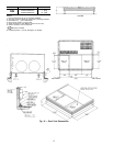
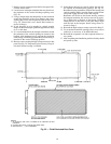
13. Cover the horizontal duct openings. Duct covers can be
ordered as an accessory or be field-fabricated as shown
in Fig. 23.
14. Reinstall the evaporator coil and indoor blower access
panels.
15. After completingunit installation, perform all safety checks
and power up unit.
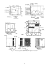
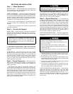
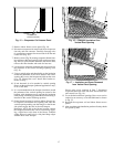
ACCESS PANEL
(REMOVE SCREWS)
Fig. 15 — Evaporator Coil Access Panel
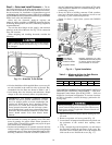
Fig. 16 — Basepan Insulation Over
Vertical Duct Opening
Fig. 17 — Insulation and Cover Removed
from Vertical Duct Opening
17