


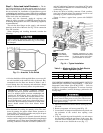

ROUTING CONTROL POWER WIRES — ICM UNITS
(24 v) — Remove knockout in the duct panel (see Fig. 28).
Remove the rubber grommet from the installer’s packet (in-
cluded with unit) and install it in the knockout opening. Route
thermostat wires through grommet providing a drip loop at
the panel. Connect low-voltage leads to the thermostat as
shown in Fig. 31-34.
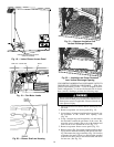
The Easy Select interface board is located in the return-air
section and is attached to the duct panel. The Easy Select
interface board is factory wired to the motor and factory de-
fault selections are preset.
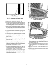
SPECIAL PROCEDURES FOR 208-V OPERATION
Make sure that the power supply to the unit is switched
OFF before making any wiring changes. Electrical shock
can cause personal injury or death.
1. Disconnect the orange transformer-primary lead from the
contactor. See unit wiring label.
2. Remove the wirenut from the terminal on the end of the
red transformer-primary lead.
3. Save the wirenut.
4. Connect the red lead to the contactor terminal from which
the orange lead was disconnected.
5. Using the wirenut removed from the red lead, insulate
the loose terminal on the orange lead.
6. Wrap the wirenut with electrical tape so that the metal
terminal cannot be seen.
Indoor blower-motor speeds may need to be changed for
208-v operation. Refer to Indoor Airflow and Airflow Ad-
justments section on page 34.
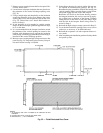
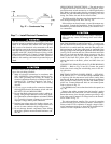
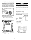
1 3/8″ DIA.
1 1/8″ DIA.
HIGH
VOLTAGE
POWER
ENTRY
(KNOCKOUT)
2″ DIA.
2″ DIA.
7/8″ DIA.
CONTROL
POWER
ENTRY*
*Knockout on rectangular-duct panel units; entry hole on round-duct
panel units.
NOTE: For rectangular duct knockout sizes, see Fig. 2-9.
Fig. 28 — Typical Duct Panel Knockouts
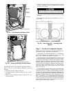
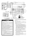
UNIT LINE WIRE
SPLICE BOX
UNIT POWER
LEAD
WIRE-BINDING
SCREW
CONTROL POWER
SPLICE BOX
Fig. 29 — Wiring Splice Boxes
Field Wiring
Splice Connections
NEC — National Electrical Code
NOTE: Use copper wire only.
Fig. 30 — Line Power Connections
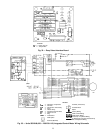
Fig. 31 — Control Connections
24