


PRE-START-UP
Failure to observe the following warnings could result
in serious personal injury:
1. Follow recognized safety practices and wear protec-
tive goggles when checking or servicing refrigerant
system.
2. Do not operate compressor or provide any electric
power to unit unless compressor terminal cover is in
place and secured.
3. Do not remove compressor terminal cover until all
electrical sources are disconnected.
4. Relieve all pressure from both high- and low-
pressure sides of the system before touching or dis-
turbing anything inside terminal box if refrigerant leak
is suspected around compressor terminals. Use ac-
cepted methods to recover refrigerant.
5. Never attempt to repair soldered connection while re-
frigerant system is under pressure.
6. Do not use torch to remove any component. System
contains oil and refrigerant under pressure. To re-
move a component, wear protective goggles and pro-
ceed as follows:
a. Shut off electrical power to unit.
b. Relieve all pressure from system using both high-
and low-pressure ports. Use accepted methods to
recover refrigerant.
c. Cut component connecting tubing with tubing cut-
ter and remove component from unit.
d. Carefully unsweat remaining tubing stubs when
necessary. Oil can ignite when exposed to torch
flame.
Use the Start-Up Checklist supplied at the end of this book
and proceed as follows to inspect and prepare the unit for
initial start-up:
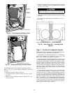
1. Remove all access panels.
2. Read and follow instructions on all WARNING, CAU-
TION, and INFORMATION labels attached to, or shipped
with, unit.
Make the following inspections:
a. Inspect for shipping and handling damages such as bro-
ken lines, loose parts, disconnected wires, etc.
b. Inspect for oil at all refrigerant tubing connections and
on unit base. Detecting oil generally indicates a re-
frigerant leak. Leak-test all refrigerant tubing connec-
tions using electronic leak detector, or liquid-soap so-
lution. If a refrigerant leak is detected, see following
Check for Refrigerant Leaks section.
c. Inspect all field- and factory-wiring connections. Be
sure that connections are completed and tight.
d. Inspect coil fins. If damaged during shipping and han-
dling, carefully straighten fins with a fin comb.
3. Verify the following conditions:
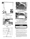
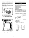
a. Make sure that outdoor-fan blade is correctly posi-
tioned in fan orifice. Leading edge of blade should be
2 in. back from condenser inlet grille or
1
⁄
2
in. maxi-
mum from fan deck.
b. Make sure that air filter(s) is in place.
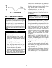
c. Make sure that condensate drain pan and trap are filled
with water to ensure proper drainage.
d. Make sure that all tools and miscellaneous loose parts
have been removed.
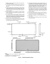
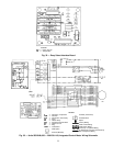
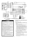
C—Contactor, Compressor
COM — Common
CTD — CompressorTime Delay
FU — Fuse
HR — Heater Relay
ICM — Integrated Control Motor
IFO — Indoor Fan On
PL — Plug
TRAN — Transformer
Field Splice
Terminal (Marked)
Fig. 34 — Unit 50SX048,060 — 208/230-3-60 Integrated Control Motor Wiring Schematic
Terminal (Unmarked)
Terminal Block
Splice
Factory Wiring
Field Control Wiring
Field Power Wiring
Accessory or Optional Wiring
To Indicate Common Potential Only.
Not to Represent Wiring
LEGEND
26