


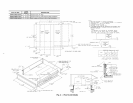
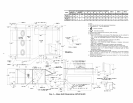
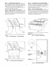
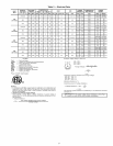
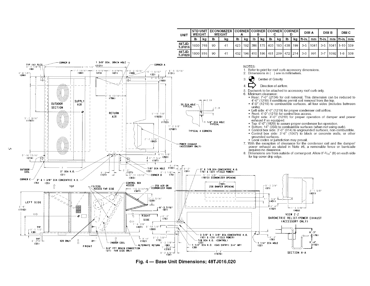
STD UNIT ECONOMIZER CORNER CORNER CORNER CORNER
UNIT WEIGHT WEIGHT A B C D
Ib kg Ib kg Ib kg Ib kg Ib kg Ib kg
48TJD,
TJF016 1650 748 90 41 423 192 386 175 403 183 438 199
48TJD,
TJF020 1800 816 90 41 432 196 410 186 461 209 472 214
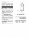
DIM A DIM B DIM C
ft-in, mm if-in, mm ft-in, mm
3-5 1041 3-5 1041 1-10 559
3-3 991 3-7 1092 1-8 508
L_
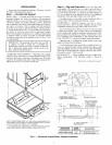
NOTES:
1. Refer to print for roof curb accessory dimensions.
2. Dimensions in ( ) are in millimeters.
3. _ Center of Gravity.
4. E_ Direction of airflow.
5. Ductwork to be attached to accessory roof curb only.
6. Minimum clearance:
• Rear: T-O" (2134) for coil removal. This dimension can be reduced to
4'-0" (1219) ifconditions permit coil removal from the top.
• 4'-0" (1219) to combustible surfaces, all four sides (includes between
units).
• Left side: 4'-0" (1219) for proper condenser coil airflow.
• Front: 4'-0" (1219) for control box access.
• Right side: 4'-0" (1219) for proper operation of damper and power
exhaust if so equipped.
• Top: 6'-0" (1829) to assure proper condenser fan operation.
• Bottom: 14" (356) to combustible surfaces (when not using curb).
• Control box side: 3'-0" (914) to ungrounded surfaces, non-combustible.
• Control box side: 3"-6" (1067) to block or concrete walls, or other
grounded surfaces.
• Local codes or jurisdiction may prevail.
7. With the exception of clearance for the condenser coil and the damper/
power exhaust as stated in Note #6, a removable fence or barricade
requires no clearance.
8. Dimensions are from outside of corner post. Allow 0'-s/l_" (8) on each side
for top cover drip edge.
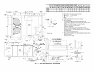
CORNER CS 3" S
iT6)
LEFT SIDE
3 9
(lt43}
3/8" OIA CONCENTRIC K.O.
(35)
TOP
iS1)
FRONT
0 3 //8"_
_0"11 _5/I_CORNER B t791
(3031
r[LTERS
ACCESSFARS]OE
VIEW Z-Z
BAROMETRIC RELIEF/POWER EXHAUST
(ACCESSORY ONLY)
SECTION A+A
Fig. 4- Base Unit Dimensions; 48TJ016,020