


Step 10 -- Make Outdoor-Air Inlet Adjust-
ments
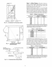
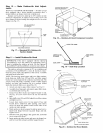
MANUAL OUTDOOR-AIR DAMPER -- All units (except
those equipped with a factory-inst_dled economizer) have a
manual outdoor-air &tmper to provide ventilation ail:
Damper can be preset to admit up to 25% outdoor air into
return-tdr compartment. To adjust, loosen secunng screws and
move &tmper to desired setting, then retighten screws to secure
dmnper (see Fig. 17).
OUTDOOR-AIR HOOD AND
MOUNTING BRACKETS
÷I
25% ADJUSTABLE
AIR DAMPER
/
/I
\ /
o g
/
SECURING SCREWS
ol
Fig. 17 -- Standard 25% Outdoor-Air
Section Details
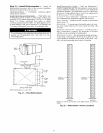
BASE
UNIT
F[_ER
PACKAGEAN[
HOOD
COMPONENTS
RETURN-AIRFILTE}
ACCESS PANEL
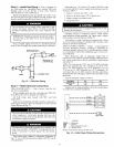
Fig. 18- Outdoor-Air Hood Component Location
PANEL
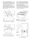
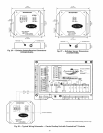
Step 11 -- Install Outdoor-Air Hood
IMPORTANT: If the unit is equipped with the optional I
EconoMiSerIV. move the outdoor air temperature sensor
I
prior to installing the outdoor air hood. See the Optional
EconoMiSerIV and EconoMiSer2 section for more details.
The outdoor- air hood is common to 25% air ventilation and
economizel: If EconoMiSerIV is used, all electrical connec-
tions have been made and adjusted at the factoly. Assemble
and install hood in the field.
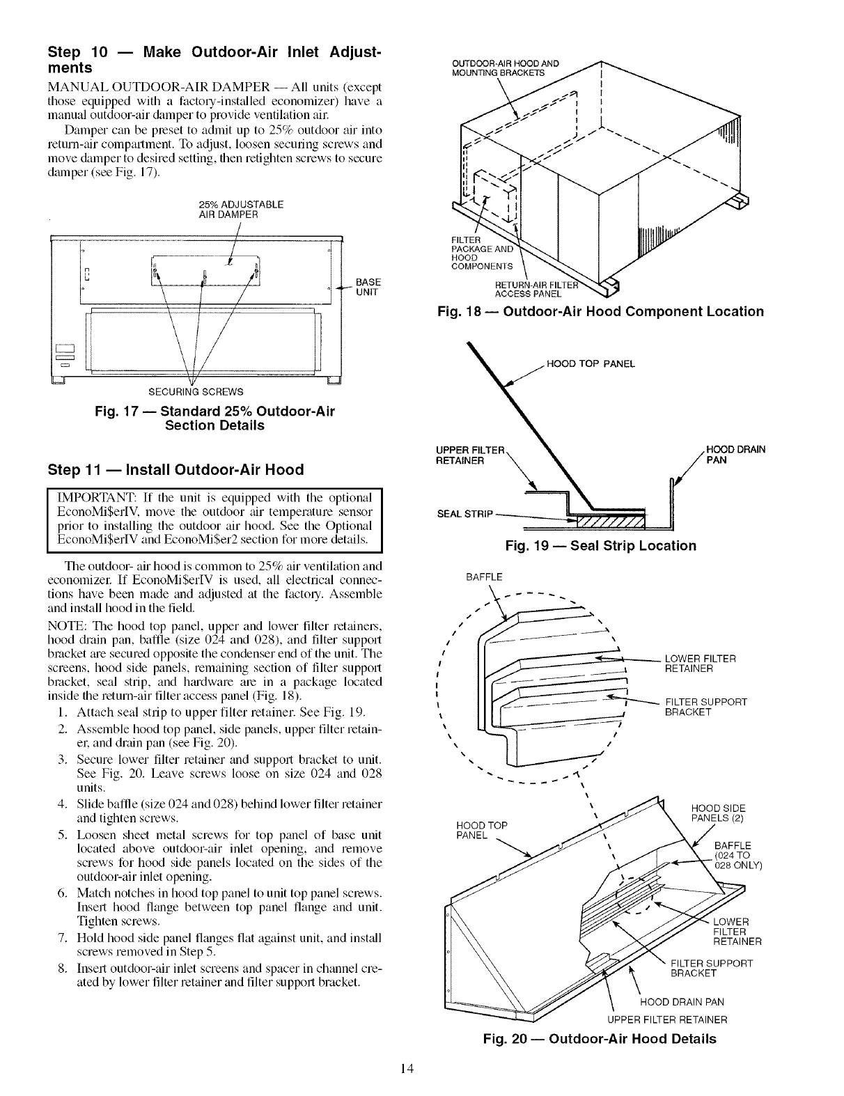
NOTE: The hood top panel, upper and lower filter retainel_,
hood drain pan, baffle (size 024 and 028), and filter support
bracket me secured opposite the condenser end of the unit. The
screens, hood side panels, remaining section of tilter support
bracket, seal strip, and hmdware are in a package located
inside the return-air filter access panel (Fig. 18).
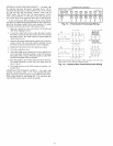
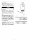
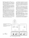
1. Attach seal strip to upper filter retainer. See Fig. 19.
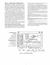
2. Assemble hood top panel, side panels, upper filter retain-
el: and dnun pan (see Fig. 20).
3. Secure lower filter rettuner and support bracket to unit.
See Fig. 20. Leave screws loose on size 024 and 028
units.
4. Slide bafile (size 024 and 028) behind lower filter retainer
and tighten screws.
5. Ix_osen sheet metal screws for top panel of base unit
located above outdoor-air inlet opening, and remove
screws for hood side panels located on the sides of the
outdoor-air inlet opening.
6. Match notches in hood top panel to unit top panel screws.
|nsert hood flange between top panel fange and unit.
Tighten screws.
7. Hold hood side panel flanges flat against unit, and install
screws removed in Step 5.
8. Insert outdoor-air inlet screens and spacer in channel cre-
ated by lower filter retainer and filter support bracket.
UPPER
RETAINER PAN
SEAL;
Fig. 19- Seal Strip Location
BAFFLE
/
\
LOWER FILTER
RETAINER
HOOD SIDE
PANELS (2)
BAFFLE
. (024 TO
028 ONLY)
LOWER
FILTER
RETAINER
FILTER SUPPORT
BRACKET
HOOD DRAIN PAN
UPPER FILTER RETAINER
Fig. 20 -- Outdoor-Air Hood Details
14