


ECONOMISERIV STANDARD SENSORS
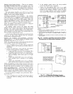
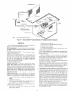
Outdoor Air Temperature (OAT) Sensor -- The outdoor air
temperature sensor (HH57AC074) is a 10 to 20 mA device
used to measure the outdoor-air temperature. The outdoor-air
temperature is used to determine when the EconoMiSerIV can
be used for free cooling. The sensor must be field-relocated.
See Fig. 32. The operating range of temperature measurement
is 40 to 100E
Supply Air Temperature (SAT) Sensor -- The supply air
temperature sensor is a 3 K tl_ermistor located at the inlet of the
indoor fan. See Fig. 33. This sensor is factory inst_flled. The op-
erating range of temperature measurement is 0° to 158 E See
Table 11 for sensor temperature/resistance values.
The temperature sensor looks like an eyelet terminal with
wires running to it. The sensor is located in the "crimp end"
and is settled from moisture.
Low Temperature Compressor Lockout Switch -- The
EconoMiSerIV is equipped with an ambient temperature lock-
out switch located in the outdoor airstrealn which is used to
lockout the compressols below a 42 F ambient temperature.
See Fig. 32.
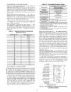
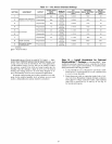
Table 11 -- Supply Air Sensor Temperature/
Resistance Values
TEMPERATURE (F) RESISTANCE (ohms)
-58 200,250
-40 100,680
-22 53,010
-4 29,091
14 15,590
32 9,795
50 5,970
68 3,747
77 3,000
86 2,416
104 1,597
122 1,080
140 745
158 525
176 376
185 321
194 274
212 203
230 153
248 115
257 102
266 89
284 70
302 55
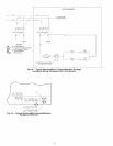
ECONOMI$ERIV CONTROL MODES
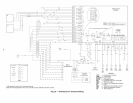
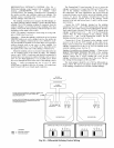
IMPORTANT: The option_d EconoMi$er2 does not include
a controllel: The EconoMiSer2 is operated by a 4 to 20 mA
signal from an existing field-supplied controller (such as
PrelnierLink TM control). See Fig. 36 for wiring information.
Determine the EconoMiSerlV control mode befole set up of
the control. Some modes of operation may lequire diffelent sen-
sors. Refer to Table 12. The EconoMi$erlV is supplied from the
factory with a supply air temperature sensor, a low temperature
complessor lockout switch, and an outdoor air temperature
sensol: This allows for operation of the EconoMi$erIV with
outdoor air diy bulb changeover control. Additional accesso-
ries can be added to _dlow for different types of changeover
control and operation of the EconoMiSerlV and unit.
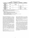
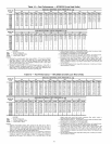
Table 12 -- EconoMi$erlV Sensor Usage
APPLICATION
Outdoor Air
Dry Bulb
Differential Dry Bulb
Single Enthalpy
Differential Enthalpy
CO2for DCV Control
using a Wall-Mounted
CO2 Sensor
CO2for DCV Control
using a Duct-Mounted
CO2 Sensor
ECONOMISERIV WITH OUTDOOR AIR
DRY BULB SENSOR
Accessories Required
None. The outdoor air dry bulb sensor
is factory installed.
CRTEMPSN002A00*
HH57AC078
HH57AC078
and
CRENTDIF004A00*
33ZCSENCO2
33ZCSENCO2t
and CRCBDiOX005A00tt
33ZCASPCO2**
*CRENTDiF004A00 and CRTEMPSN002A00 accessories are used on
many different base units. As such, these kits may contain parts that
will not be needed for installation.
1-33ZCSENCO2 is an accessory CO2 sensor.
**33ZCASPCO2 is an accessory aspirator box required for duct-
mounted applications.
1-1-CRCBDIOX005A00 is an accessory that contains both 33ZCSENCO2
and 33ZCASPCO2 accessories.
Outdoor DLy Bulb Changeover -- The standard controller is
shipped from the factory configured for outdoor &y bulb
changeover control. The outdoor air and supply air temperature
sensors me included as standard. For this control mode, the
outdoor temperature is compmed to an adjustable set point se-
lected on the control. If the outdoor-air temperature is above
the set point, the EconoMiSerIV will adjust the outdoor-air
dampers to minimum position. If the outdoor-air temperature is
below the set point, the position of the outdoor-air dampers will
be controlled to provide free cooling using outdoor ail: When
in this mode, the LED next to the free cooling set point potenti-
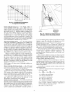
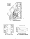
ometer will be on. The changeover temperature set point is
controlled by the free cooling set point potentiometer located
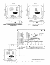
on the control. See Fig. 37. The sc_fle on the potentiometer is A,
B, C, and D. See Fig. 38 for the corresponding temperature
changeover values.
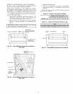
Differential Dry Bulb Control -- For differential dry bulb
control the standard outdoor @ bulb sensor is used in conjunc-
tion with an additional accessory return air sensor (part number
CRTEMPSN002A00). The accessory sensor must be mounted
in the return airstream. See Fig. 39.
In this mode of operation, the outdoor-air temperature is
compared to the return-air temperature and the lower tempera-
ture airstream is used for cooling. When using this mode of
changeover control, turn the free cooling/enthalpy set point
potentiometer fully clockwise to the D setting. See Fig. 37.
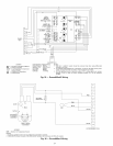
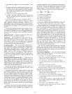
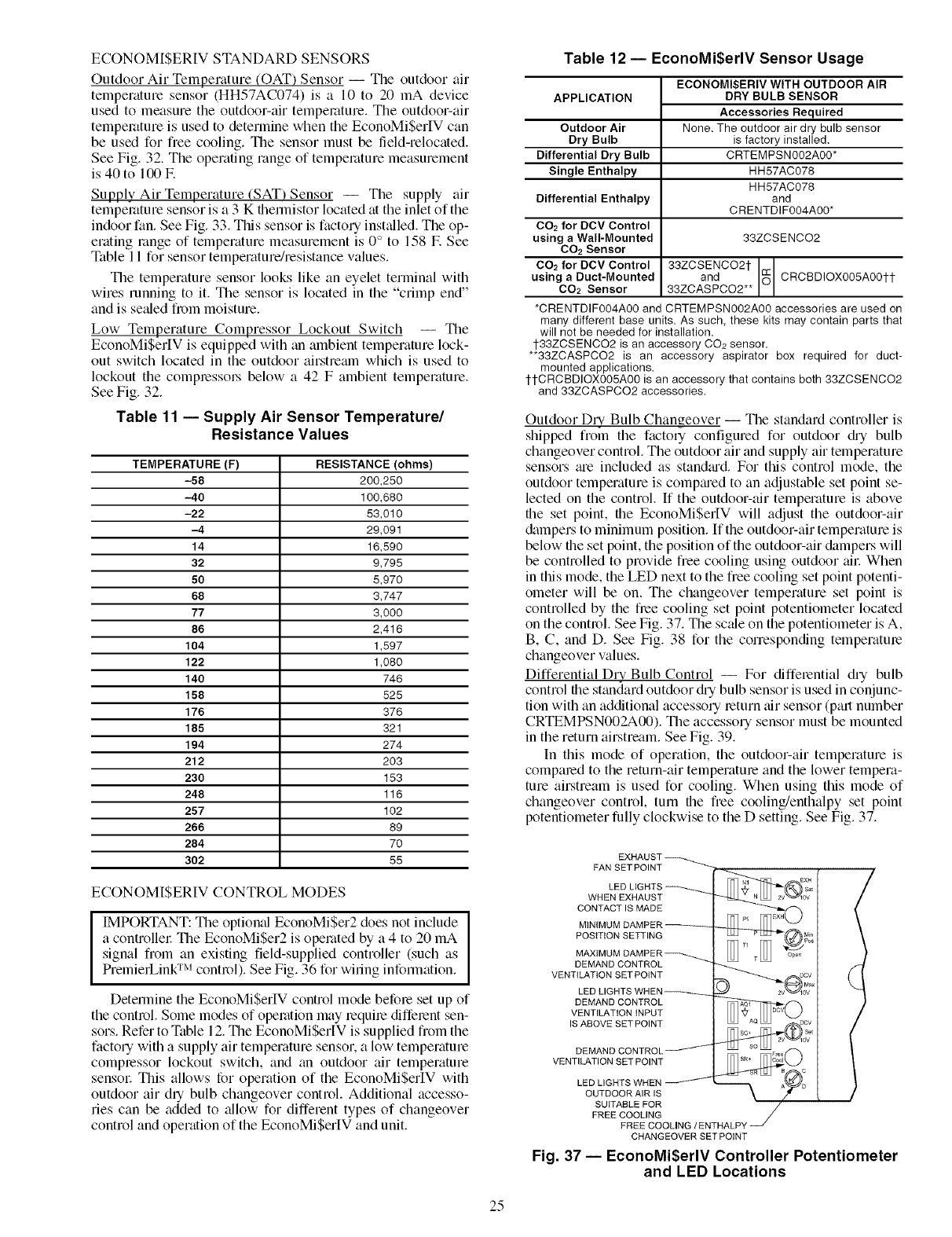
EXHAUST
FAN SET POINT
LED LIGHTS
WHEN EXHAUST
CONTACT IS MADE
MINIMUM DAMPER
POSITION SETTING
MAXIMUM DAMPER
DEMAND CONTROL
VENTILATION SET POINT
LED LIGHTS WHEN
DEMAND CONTROL
VENTILATION iNPUT
IS ABOVE SET POINT
DEMAND CONTROL
VENTILATION SET POINT
LED LIGHTS WHEN
OUTDOOR AIR IS
SUITABLE FOR
FREE COOLING
FREE COOLING / ENTHALPY
CHANGEOVER SET POINT
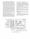
Fig. 37 -- EconoMi$erlV Controller Potentiometer
and LED Locations
25