OPTIONAL ECONOMISERIV AND ECONOMISER2 --
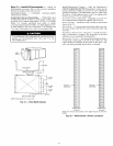
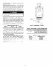
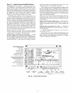
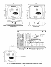
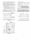
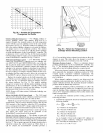
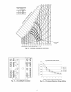
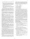
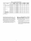
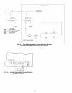
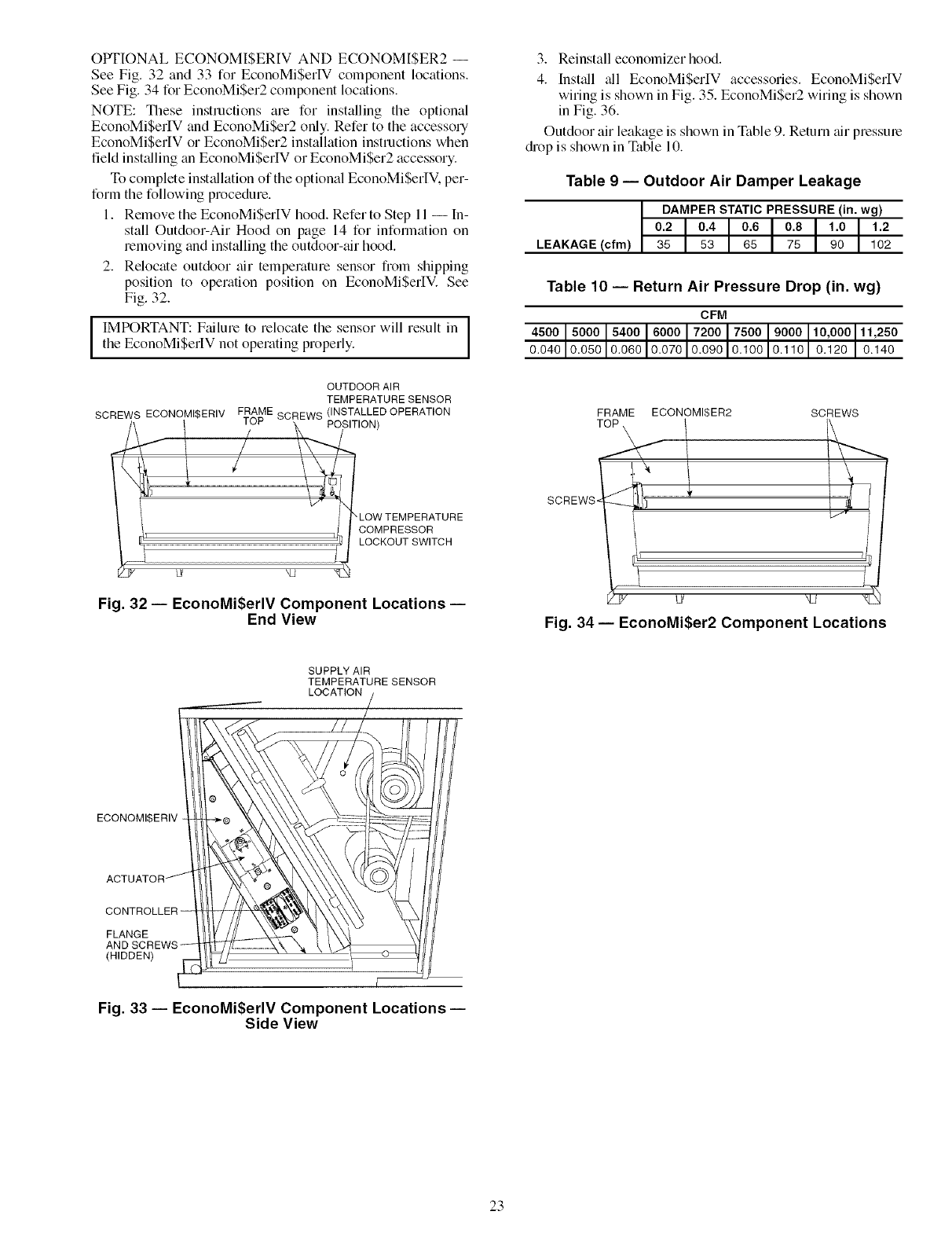
See Fig. 32 and 33 for EconoMiSerIV component locations.
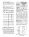
See Fig. 34 for EconoMi$er2 component locations.
NOTE: These instructions are for installing the optional
EconoMiSerIV and EconoMiSer2 only. Refer to the accessory
EconoMiSerIV or EconoMiSer2 installation instructions when
field installing an EconoMi$erIV or EconoMiSer2 accessory.
To complete inst_fllation of the optional EconoMiSerIV. per-
form the following procedure.
1. Remove the EconoMiSerIV hood. Refer to Step 11 -- In-
stall Outdoor-Air Hood on page 14 for information on
removing and installing the outdoor-air hood.
2. Relocate outdoor air temperature sensor from shipping
position to operation position on EconoMiSerIV. See
Fig. 32.
I MPORTANT: Failure to relocate the sensor will result in
the EconoMiSerIV not operating properly.
SCREWS ECONOMI$ERIV
OUTDOOR AIR
TEMPERATURE SENSOR
FRAME SCREWS (INSTALLED OPERATION
IUb'
POSITION)
LOW TEMPERATURE
COMPRESSOR
LOCKOUT SWITCH
Fig. 32--EconoMiSerlVComponent Locations--
End View
3. Reinstall economizer hood.
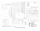
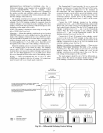
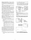
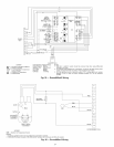
4. Install _dl EconoMiSerIV accessories. EconoMiSerlV
wiring is shown in Fig. 35. EconoMi$er2 wiring is shown
in Fig. 36.
Outdoor air leakage is shown in Table 9. Return air pressure
drop is shown in Table 10.
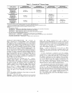
Table 9 -- Outdoor Air Damper Leakage
DAMPERSTATICPRESSURE (in. wg)
0.2 0.4 0.6 0.8 1.0 1.2
LEAKAGE (cfm) 35 53 65 75 90 102
Table 10 -- Return Air Pressure Drop (in. wg)
CFM
4500 5000 5400 6000 7200 7500 9000 10,000 11,250
0.040 0.050 0.060 0.070 0.090 0.100 0.110 0.120 0.140
FRAME ECONOMISER2 SCREWS
SCREWS.
/
i_ 7
j u /J N2
Fig. 34- EconoMi$er2 Component Locations
SUPPLY AIR
TEMPERATURE SENSOR
LOCATION
ECONOMI$ERIV
FLANGE
(HIDDEN)
[
Fig. 33 -- EconoMi$erlV Component Locations-
Side View
23


